Multi-generator leading-phase operation method considering generator maximum leading-phase capacity

A generator and phase advance technology, applied in reactive power compensation, reactive power adjustment/elimination/compensation, etc., can solve problems such as excess reactive power, degradation of system power quality, affecting the safe and stable operation of the power grid, and reduce power grids. The effect of operating voltage and ensuring safe and stable operation

Active Publication Date: 2017-05-24
ELECTRIC POWER RESEARCH INSTITUTE OF STATE GRID SHANDONG ELECTRIC POWER COMPANY +1
View PDF3 Cites 4 Cited by
  • Summary
  • Abstract
  • Description
  • Claims
  • Application Information

AI Technical Summary

Problems solved by technology

Most of the reactive power compensation devices installed in the system are capacitors, which do not have flexible switching functions. If the reactive power compensation devices fail to withdraw in time during nights and holidays when the system load is low, it will cause excess reactive power in the system. The operating voltage of the power grid is high, close to or even higher than the upper limit of the o

Method used


Image

  • Multi-generator leading-phase operation method considering generator maximum leading-phase capacity
  • Multi-generator leading-phase operation method considering generator maximum leading-phase capacity

Examples


Embodiment Construction

[0023] The present invention will be further described below in conjunction with the accompanying drawings and embodiments.

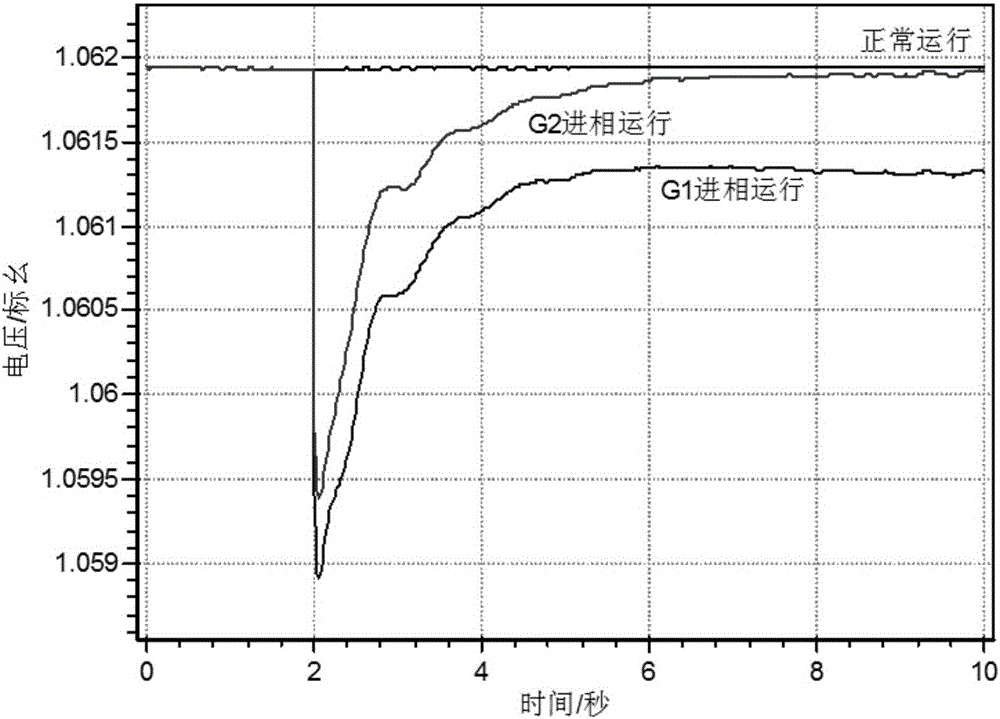
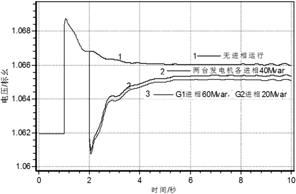
[0024] Taking an actual power grid as the actual simulation model, in which the rated power of generators G1 and G2 are both 300MW, considering the influence of factors such as the temperature of the generator stator side core and metal structural parts, system voltage, power angle stability and system static stability limit , G1 and G2 rated power running maximum phase advance capacity is 60Mvar. The rated voltage of the observation node in the power grid is 500kV. When the power grid runs normally for 1 second, the reactive power is excessive, and the generator needs to absorb 80Mvar of reactive power. This requires two generators to allocate the phase-in-phase capacity to ensure the operation of the power grid. The voltage can be reduced quickly to ensure the safe and stable operation of the system.

[0025] Calculate the phase-advancing factors of ...


PUM


Abstract

The invention discloses a multi-generator leading-phase operation method considering generator maximum leading-phase capacity. The method comprises the following steps: selecting some bus node in a network as an observation node and observing drop amount of bus voltage of the selected node; according to the feature that different generators absorb same reactive power, observing drop amount of node bus voltage correspondingly, and calculating leading-phase influence factors of the different generators; and carrying out ranking according to the values of the leading-phase influence factors, and allocating reactive power needed to be absorbed by leading-phase operation according to the rank. The method is characterized in that, through cooperation of a plurality of generator sets, grid operating voltage is reduced as quickly as possible under the condition of considering the generator maximum leading-phase capacity. Compared with a conventional depth leading-phase operation method of random single or multiple generators, the method has larger flexibility, can improve voltage drop rate and can maintain system stability as far as possible under the condition of ensuring the generator maximum leading-phase capacity.

Description

technical field [0001] The invention relates to a multi-machine phase advance method considering the maximum phase advance capability of generators. Background technique [0002] my country's power load consumption area and resource mineral deposit area are extremely unbalanced, and with the proposal of the global energy Internet theme, UHV AC transmission has been widely developed, while the installed capacity of power plants has continued to increase, and the phase-to-phase and relative-to-ground capacitance of transmission lines has also increased. becomes larger, which causes the capacitive reactive power of the system to increase continuously. In addition to traditional AC transmission requiring a large number of reactive power compensation devices to make up for the lack of system reactive power during peak loads, with the development of power electronic transmission methods such as high-voltage DC transmission and flexible AC transmission, it is also necessary to inves...

Claims


Application Information

Patent Timeline
IPC IPC(8): H02J3/18
CPCH02J3/18Y02E40/30
Inventor 李宽赵斌超李玉敦王宏杨超张婉婕张国辉王昕
Owner ELECTRIC POWER RESEARCH INSTITUTE OF STATE GRID SHANDONG ELECTRIC POWER COMPANY
Why Eureka
Try Eureka