Control method of inversion circuit and electrical energy transformation device

An inverter circuit and electric energy conversion technology, which is applied to circuit devices, output power conversion devices, and AC power input to DC power output. Realize the effect of function reuse

Inactive Publication Date: 2017-05-24
GREE ELECTRIC APPLIANCES INC
View PDF4 Cites 2 Cited by
  • Summary
  • Abstract
  • Description
  • Claims
  • Application Information

AI Technical Summary

Problems solved by technology

[0005] Therefore, the technical problem to be solved by the present invention is that the wireless charging circuit in the prior art has a single function and can only realize the wireless charging function

Method used


Image

  • Control method of inversion circuit and electrical energy transformation device
  • Control method of inversion circuit and electrical energy transformation device
  • Control method of inversion circuit and electrical energy transformation device

Examples


Embodiment 1

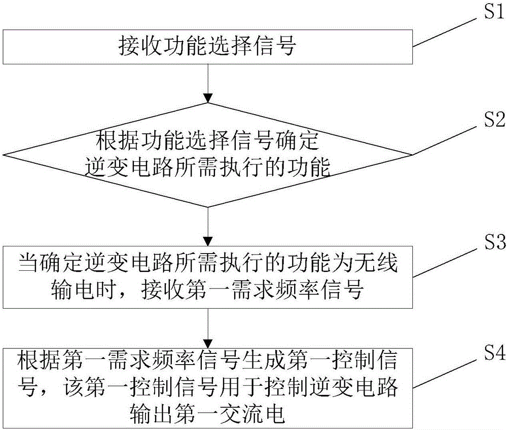
[0033] Such as figure 1 As shown, this embodiment provides a control method for an inverter circuit, including the following steps:

[0034] S1: Receive a function selection signal, the function selection signal can be set by a code switch, the operation of the code switch is convenient and the cost is low.

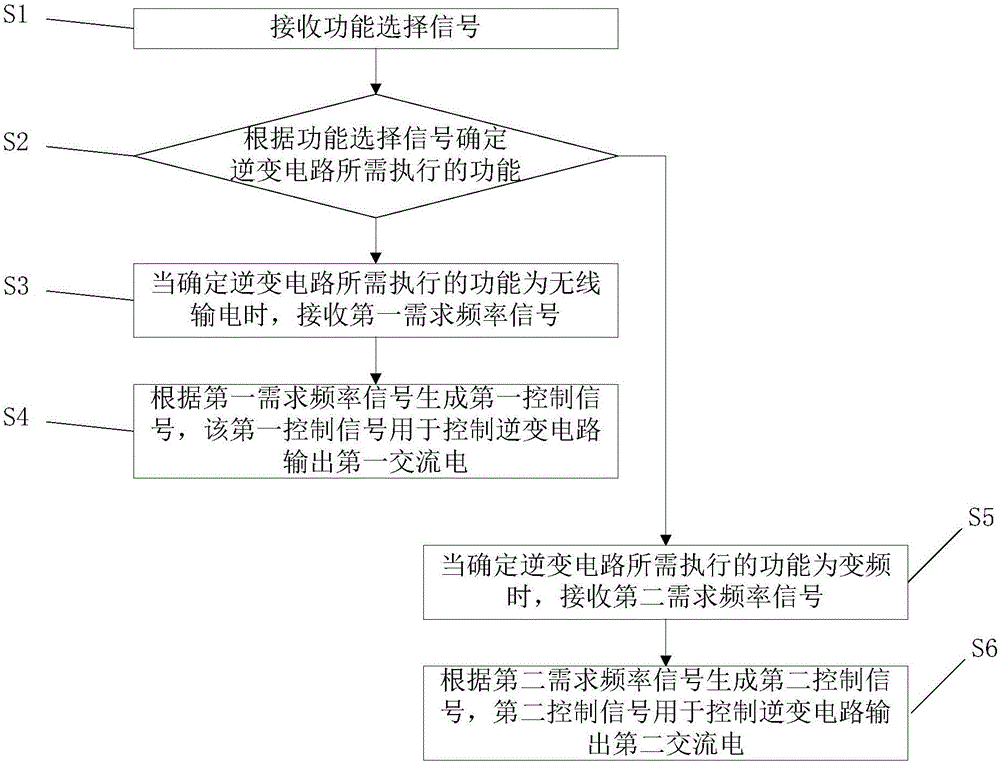
[0035] S2: Determine the functions to be performed by the inverter circuit according to the function selection signal. The functions to be performed include wireless power transmission and frequency conversion, that is, the inverter circuit has two working modes, which are switched by the dial switch of.

[0036] S3: When it is determined that the function to be performed by the inverter circuit is wireless power transmission, receiving a first required frequency signal.

[0037] S4: Generate a first control signal according to the first demand frequency signal, the first control signal is used to control the inverter circuit to output the first alternating current, the...

Embodiment approach

[0048] As another optional implementation manner of the present application, the method further includes the following steps:

[0049] First, obtain the actual frequency of the second alternating current;

[0050] Then, acquire a second difference between the actual frequency of the second alternating current and the second required frequency;

[0051] Finally, the second control signal is adjusted according to the second difference.

[0052] The control method of the inverter circuit provided in this embodiment needs to detect the actual frequency of the second alternating current output by the inverter circuit when it controls the inverter circuit to be in the frequency conversion mode, and then compare it with the second required frequency and obtain Finally, the second control signal is adjusted according to the difference, so as to realize the feedback control, so that the frequency of the alternating current output by the inverter circuit can be accurately adjusted acco...

Embodiment 2

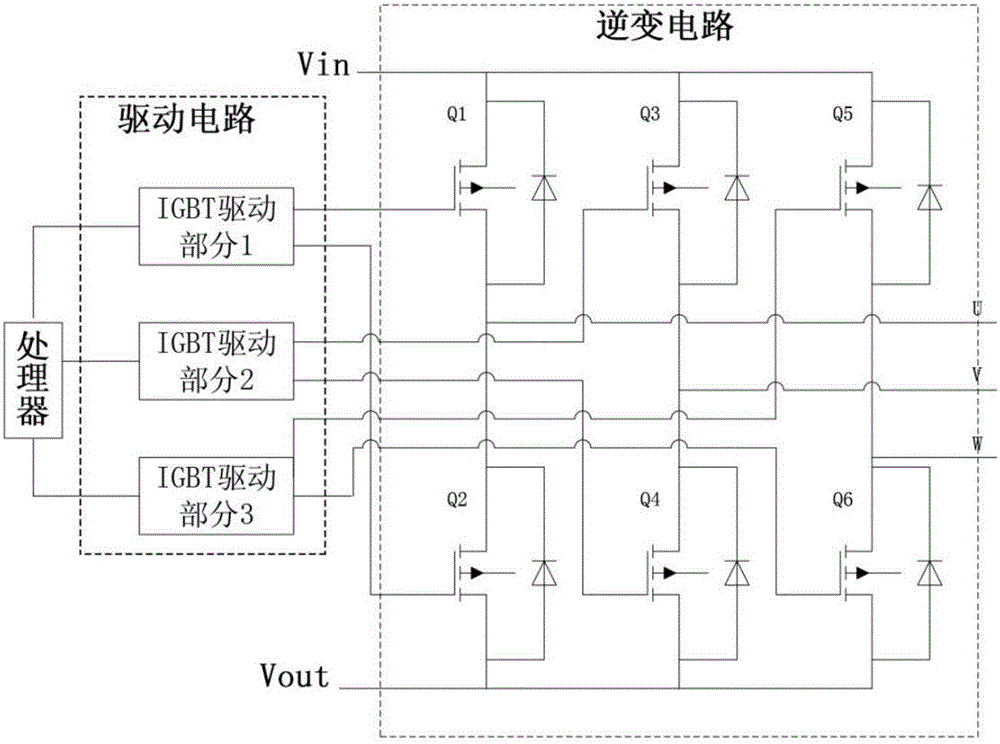
[0054] Such as image 3 As shown, this embodiment provides a power conversion device, including:

[0055] inverter circuit;

[0056] The driving circuit is used to control the switching transistor in the inverter circuit to be turned on or off. The switching transistor can be an IGBT tube, and the driving circuit is specifically selected from an isolated driving circuit to ensure circuit safety;

[0057] The processor is configured to send a control signal to the driving circuit according to the control method of the inverter circuit provided in Embodiment 1 above. When the processor determines that the user currently selects the inverter circuit to be in the wireless power transmission mode according to the position of the dial switch, that is, outputs the first control signal according to the received first demand frequency signal, and the drive circuit controls the inverter circuit according to the first control signal. The switch transistor is turned on or off at a certa...


PUM


Abstract

The invention provides a control method of an inversion circuit and an electrical energy transformation device and belongs to the technical field of charging power supply. The control method of the inversion circuit comprises the following steps: receiving function selection signals; determining functions required to be performed by the inversion circuit according to the function selection signals, wherein the functions required to be performed comprise wireless power transmission and frequency conversion; receiving a first required frequency signal when determining that the function required to be performed by the inversion circuit is wireless power transmission; generating a first control signal according to the first required frequency signal, wherein the first control signal is used for controlling the inversion circuit to output first alternating current; the frequency of the first alternating current is first required frequency; the first required frequency is preset fixed frequency. The control method is capable of controlling the inversion circuit to be in different operation modes and implement different functions, so that the functions of the inversion circuit are multiplexed.

Description

technical field [0001] The invention relates to the technical field of charging and power supply, in particular to a control method of an inverter circuit and a power conversion device. Background technique [0002] With the development of wireless technology, wireless power transmission is a new type of power transmission. The so-called wireless power transmission refers to the wireless transmission of electric energy by coupling with electromagnetic fields or other substances without cables. Wireless charging uses the principle of "resonance" in physics - two objects that vibrate at the same frequency can transfer energy efficiently. Wireless power transmission includes three common wireless charging methods: coupled inductive, electromagnetic resonance, and optical coupling. Among them, electromagnetic resonance can achieve relatively high efficiency and is widely used in various fields of the wireless charging industry. [0003] A wireless charging circuit in the prior...

Claims


Application Information

Patent Timeline
Patent Type & Authority Applications(China)
IPC IPC(8): H02J50/12H02M7/5387
CPCH02M7/5387
Inventor 赵元明许敏雷龙杨中厦赵智杰
Owner GREE ELECTRIC APPLIANCES INC
Why Eureka
Try Eureka