
CMOS power amplifier with high linearity

A power amplifier, high linearity technology, applied in power amplifiers, amplifiers, DC-coupled DC amplifiers, etc., can solve the problems of not considering the influence of nonlinearity, limited linearity improvement, and limited application range, etc., to achieve linearity improvement , Improve linearity and improve efficiency

Active Publication Date: 2017-05-24
RDA MICROELECTRONICS SHANGHAICO LTD
View PDF6 Cites 14 Cited by
  • Summary
  • Abstract
  • Description
  • Claims
  • Application Information

AI Technical Summary

Problems solved by technology

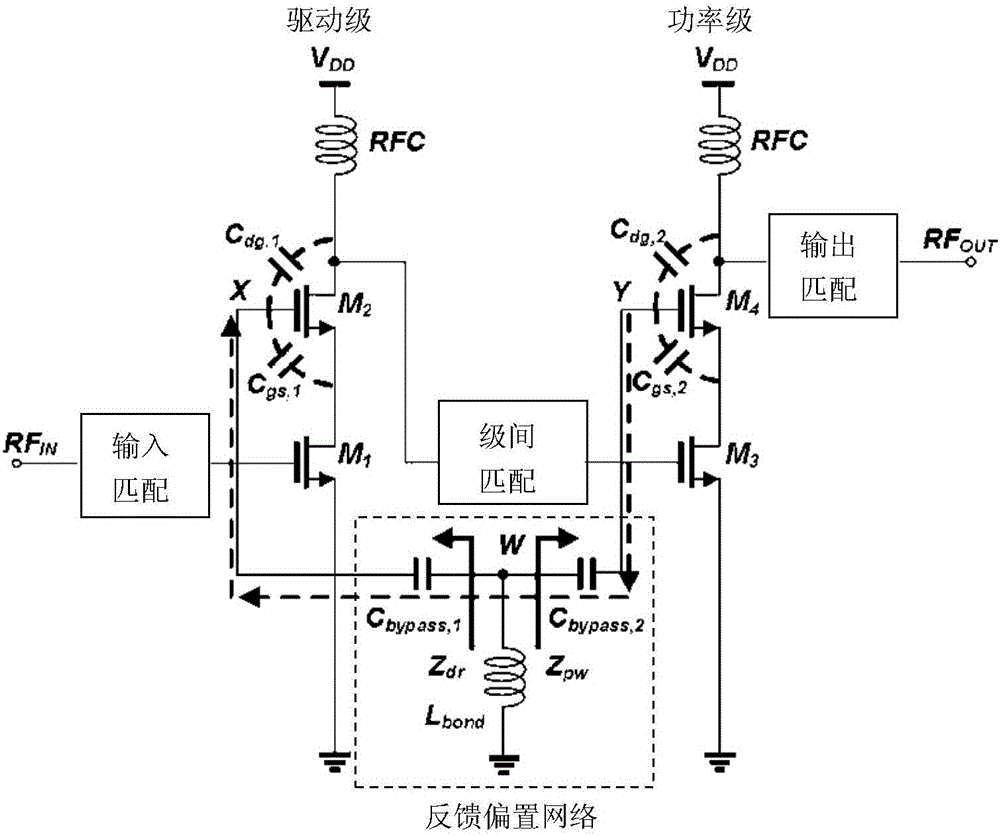
However, this solution does not consider the influence of the common source transistors M1 and M3 of the driver stage and power stage on the nonlinearity, and the improvement of linearity is limited
And this solution can only be used for power amplifiers with multi-stage structure, which limits its scope of application

Method used


Image

  • CMOS power amplifier with high linearity
  • CMOS power amplifier with high linearity
  • CMOS power amplifier with high linearity

Examples


Embodiment Construction

[0022] The high linearity CMOS power amplifier provided in this application is used to amplify the power of the input signal in to obtain the output signal out. The input signal in of the power amplifier may be a radio frequency signal or a baseband signal or the like.

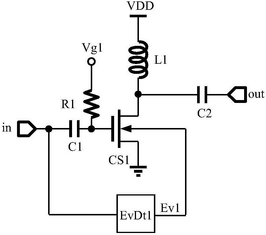
[0023] see image 3 , which is Embodiment 1 of the high linearity CMOS power amplifier provided by the present application. The embodiment 1 includes a common source amplifier CS1 and an envelope detector EvDt1. The common source amplifier CS1 receives the input signal in, amplifies its power and outputs the output signal out. On the one hand, the gate of the common source amplifier CS1 is connected to the input terminal of the power amplifier through the capacitor C1, and on the other hand, it receives the gate bias voltage Vg1 through the resistor R1. The drain of the common source amplifier CS1 is connected to the output terminal of the power amplifier through the capacitor C2 on the one hand, and receiv...


PUM


Abstract

The invention discloses a CMOS power amplifier with high linearity. The CMOS power amplifier comprises an amplifier unit and an envelope detection unit. The amplifier unit comprises one or more power transistors used for performing power amplification on input signals to obtain output signals. The envelope detection unit detects the input signals of the power transistors and generates envelope signals to serve as substrate bias voltages of the corresponding power transistors. According to the CMOS power amplifier disclosed by the invention, as the substrate voltages of the power transistors are adjusted by the envelope signals of the input signals of the power transistors, the linearity of the power amplifier can be effectively improved, and compared with the prior art of adjusting the grid voltages or supply voltages of the power transistors by adopting the envelope signals, the linearity is improved more effectively. The CMOS power amplifier further has a certain effect of improving the efficiency of the power amplifier.

Description

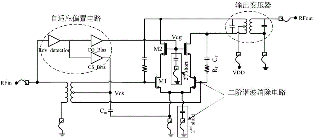
technical field [0001] The present application relates to a CMOS power amplifier, in particular to a substrate bias CMOS power amplifier. Background technique [0002] Designing power amplifiers using standard CMOS technology faces challenges in many performance indicators, and some solutions have been proposed to improve the linearity of CMOS power amplifiers. [0003] In December 2013, "IEEE TRANSACTIONS ON MICROWAVETHEORY AND TECHNIQUES" (IEEE TRANSACTIONS ON MICROWAVETHEORY AND TECHNIQUES) has an article "Linearity of CMOS Cascode Power Amplifiers by Adaptive Bias Control" "(Linearization of CMOS Cascode Power Amplifiers Through Adaptive Bias Control), this article records the linearization techniques of cascode power amplifiers using adaptive bias circuits, such as figure 1 shown. First, a common source amplifier M1 and a common gate amplifier M2 are cascaded to form a cascode amplifier, and then two cascode amplifiers form a differential structure, and then the envel...

Claims


Application Information

Patent Timeline
Patent Type & Authority Applications(China)
IPC IPC(8): H03F1/32H03F1/02H03F3/21H03F3/45
CPCH03F1/0211H03F1/3205H03F1/3211H03F3/21H03F3/45394H03F2203/45024
Inventor 林甲富刘冠山郭天生贾斌
Owner RDA MICROELECTRONICS SHANGHAICO LTD
Learn More