Test system and test method of wireless network device
A technology of wireless network equipment and test system, which is applied in the direction of transmission system, wireless communication, receiver monitoring, etc., can solve the problems of long test time, multiple manpower and material costs, and construction costs, so as to save test time and reduce test labor costs , the effect of strong intelligence
- Summary
- Abstract
- Description
- Claims
- Application Information
AI Technical Summary
Problems solved by technology
Method used
Image
Examples
no. 1 example
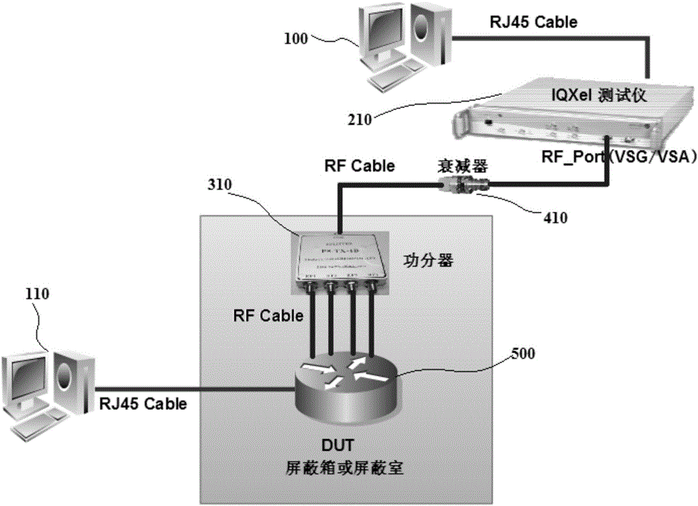
[0106] Such as Figure 4 It is shown in the schematic diagram of the system structure of the first embodiment of the present invention:
[0107] This embodiment provides a test system for intelligent wireless network equipment:
[0108] A test system for wireless network equipment, including at least a test platform 100 and a first tester 210,
[0109] The test platform 100 is configured to initialize the wireless network device 500 to be tested, and coordinate the interworking between the wireless network device 500 and the first tester 210 during the test;
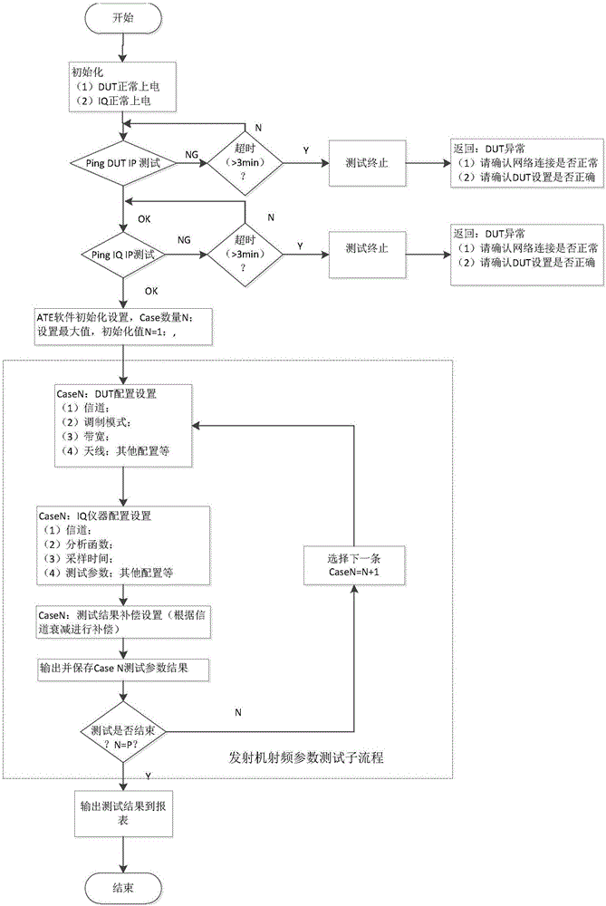
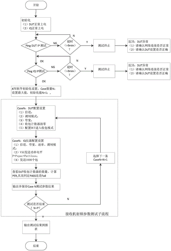
[0110] The first tester 210 is configured to perform a transmitter radio frequency parameter test or a receiver radio frequency test on the first frequency (2.4G) wireless port or the second frequency (5G) wireless port of the wireless network device 500 to be tested. Parametric testing.
[0111] The wireless network device 500 to be tested includes, but is not limited to, a Bluetooth device, a WiFi device or a LiFi d...
no. 2 example
[0123] On the basis of Example 1, as Figure 5 It is a schematic diagram of the system structure of the second embodiment of the present invention:
[0124] Still further preferably, this embodiment also provides another test system for smart wireless network equipment: the test system described above, the test system also includes a second tester 220,
[0125] The first tester 210 is configured to perform a transmitter radio frequency parameter test or a receiver radio frequency parameter test on the first frequency (2.4G) wireless port of the wireless network device 500 to be tested;
[0126] The second tester 220 is configured to perform a transmitter radio frequency parameter test or a receiver radio frequency parameter test on the second frequency (5G) wireless port of the wireless network device 500 to be tested;
[0127] The test platform 100 is configured to initialize the wireless network device 500 under test, and coordinate the interworking between the wireless net...
no. 3 example
[0166] The technical problem to be solved in this embodiment is aimed at the status quo of the existing technology, thereby providing a test system for radio frequency static parameters, through which the test system saves half the test time compared with the original test system, and saves manpower and material resources and construction costs.
[0167] Such as Figure 5 As shown in the schematic diagram of the system structure of the second embodiment of the present invention, this embodiment uses two multi-port power splitters 310, 320 to pass through multi-RF Cable lines and solid attenuators 410, 420 to connect the 2.4G ANT and 5G ANT of the machine under test 500 Connection, connected to the IQ tester 210, 220 respectively, the ATE automation platform 100 accesses and controls the device under test (DUT) 500, the IQ tester (IQ1) 210, and the IQ tester (IQ2) 220 respectively through the RJ45 Cable line. The ATE automation platform 100 controls the IQ tester and the devic...
PUM
 Abstract
Description
Claims
Application Information
 - R&D
- Intellectual Property
- Life Sciences
- Materials
- Tech Scout
- Unparalleled Data Quality
- Higher Quality Content
- 60% Fewer Hallucinations
Browse by: Latest US Patents, China's latest patents, Technical Efficacy Thesaurus, Application Domain, Technology Topic, Popular Technical Reports.
© 2025 PatSnap. All rights reserved.Legal|Privacy policy|Modern Slavery Act Transparency Statement|Sitemap|About US| Contact US: help@patsnap.com


