[0070] figure 1 A simplified schematic illustration showing the construction of an infusion device into which the device according to the invention can be integrated.
[0071] For the infusion of medical solutions, a hose set (23) is used, which is connected to the patient through the vascular access of the vein. The contents of the infusion container (25) flow by means of gravity into the patient via the droplet chamber (24) or are introduced to the patient via the pump (26). The injection site (28) for the medicine can be integrated into the hose set. Said injection site (28) is suitable for coupling the device (2) according to the invention. It is also possible to couple the device according to the invention at the droplet chamber (24). The device according to the invention can furthermore be designed as an integral part of the infusion tube set.
[0072] figure 2 A simplified schematic illustration showing the construction of an extracorporeal therapy device as an example of a hemodialysis device into which the device according to the invention can be integrated.
[0073] Blood is usually drawn from the patient at an arterio-venous fistula during hemodialysis. The part of the extracorporeal circulation before the dialyzer is called the arterial part and the part after the dialyzer is called the venous part. Extracorporeal circulation in hemodialysis, as well as in other extracorporeal treatment methods, usually takes place entirely within the tubing or cassette set (23). The drop chamber (24) is usually integrated into the part of the circulating vein in order to expel air bubbles that may arise. Also in tube or cassette sets for extracorporeal treatment there is usually an injection site ( 28 ) for the drug which is suitable for coupling the device ( 2 ) according to the invention. as from figure 2 As can be seen, the drug is delivered by means of the device (2) according to the invention into the arterial part (A) of the extracorporeal circulation, before (B) and after (D) the drop chamber into the venous part of the circulation Addition in or to the droplet chamber itself (C) is feasible. The device according to the invention can furthermore be designed as an integral part of a tube or a cassette set for extracorporeal therapy and preferably a hemodialysis tube or a cassette set.
[0074] image 3 A three-dimensional representation of the device ( 2 ) according to the invention is shown. The device (2) consists of a first fixing member (4) for accommodating a connecting mechanism (8), a second fixing member (5) for accommodating a puncture bottle (1), a manipulation device (7) and a connecting mechanism ( 8) Composition.
[0075] The manipulation device (7) is connected with the lifting rod (9), and the second fixing member (5) is fixed at the lifting rod (9). The manipulating means (7) is used to move the lifting rod (9) and the second fixing member (5) along the axis X.
[0076] The turntable is integrated (6) into the first fixing. In the rotary disk, the connecting means ( 8 ) are fixed in the vertical direction by means of the undercuts ( 6 ′) and in the horizontal direction by means of the latching noses ( 6 ″).
[0077] In one embodiment, the device according to the invention can be permanently integrated into a medical treatment unit, preferably into an infusion device or an extracorporeal treatment unit, in particular into a hemodialysis machine, by means of a machine holder ( 3 ), or Releasably fastened there.
[0078] The device can thus be used in methods of medical technology, in particular in methods for infusion or extracorporeal therapy, preferably in hemodialysis methods.
[0079] The device has not only rigid elements such as, for example, connecting means ( 8 ), but also soft elements such as, for example, seals ( 17 ). The rigid material is preferably made of polymers suitable for this application, such as eg polycarbonate (PC), polypropylene (PP), polyethylene (PE), polystyrene (PS), polyvinyl chloride (PVC) ), polyethylene terephthalate (PET), polybutylene terephthalate (PBT), acrylonitrile-butadiene-styrene (ABS), and copolyesters.
[0080] The soft material consists of a suitable elastic material, preferably an elastomer, such as, for example, silicone-rubber, styrene-ethylene-butyl-styrene (SEBS), styrene-ethylene-propylene-styrene (SEPS) ), styrene-isoprene-styrene (SIS), styrene-butadiene-styrene (SBS), polyurethane (PU), polyisoprene, thermoplastic elastomer (TPE), natural rubber (NR) and latex.
[0081] Figure 4a or 5a shows a three-dimensional representation of the connecting means ( 8 ) with closed or open flow paths.
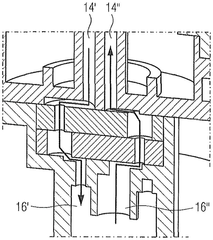
[0082] Figure 4b Or 5b shows a three-dimensional representation of the connecting means ( 8 ) with closed or open flow paths in longitudinal section.
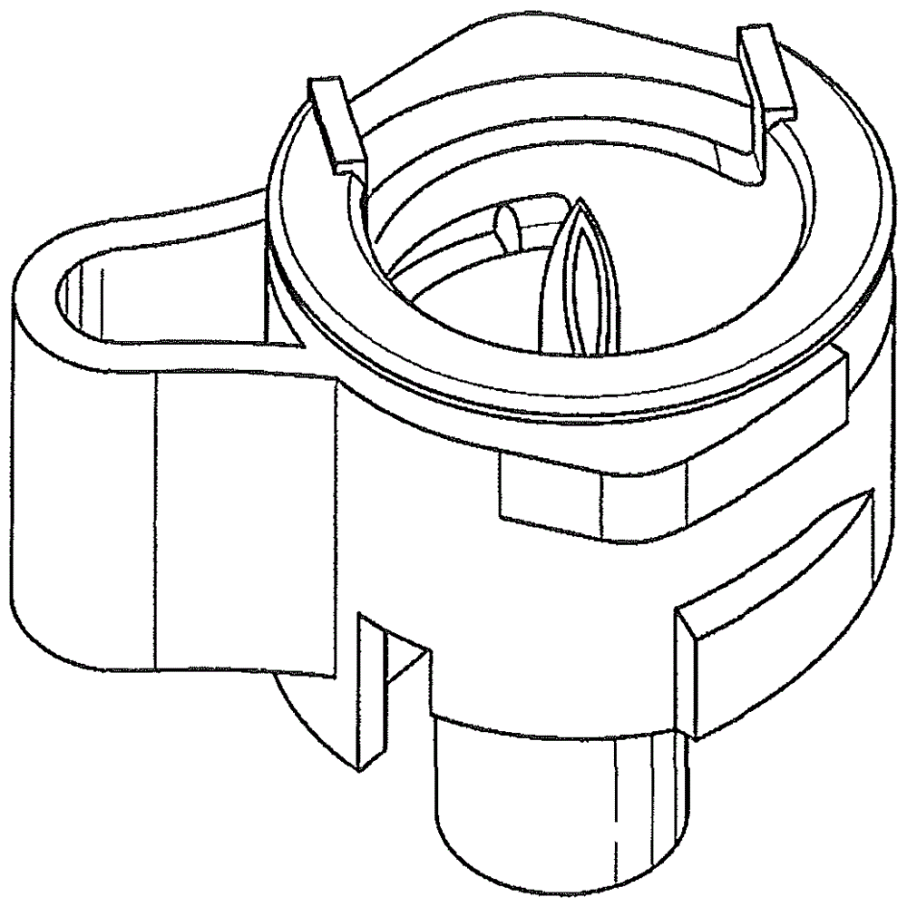
[0083] Depend on Figure 4a As can be seen from /b and 5a/b, the connecting mechanism (8) consists of an annular housing (13) with an active surface (15), an inner part (12) which is also annular, a piercing device (14), a seal (13). 17) and the hose connection end (16).
[0084] The housing ( 13 ) of the connecting mechanism ( 8 ) is mounted rotatably around the inner part ( 12 ) in the function of the valve. On the active surface ( 15 ), the housing ( 13 ) can be guided reliably and easily during rotation about the inner part ( 12 ), that is to say without great force consumption.
[0085] Since the puncture bottle (1) is mainly made of rigid material, the transferred contents must be replaced when the contents of the puncture bottle (1) are transferred into the container or into the fluid line so that the flow through does not end. volume of the thing. The puncturing device ( 14 ) of the device ( 2 ) according to the invention must therefore have two line paths. A first line path ( 14 ′) for transferring the contents of the puncture bottle ( 1 ) into a container or into a fluid line, through which a fluid, preferably a gas, can flow in into the puncture bottle (1). As a result, the outflowing contents of the puncture bottle ( 1 ) are replaced and the generation of a negative pressure which would deplete the flow through is avoided. The piercing device (14) can be implemented in the form of two separate hollow needles, needles or staples, preferably in the form of a double lumen staple.
[0086] Ideally, the connecting means ( 8 ) are furthermore designed such that the cover ( 29 ) can be placed on the piercing device ( 14 ) in a sealing manner. The cover ( 29 ) can preferably be made of an elastic material, so that the cover ( 29 ) is squeezed when connecting the piercing bottle ( 1 ) and releases the piercing device ( 14 ) and when disconnecting Slide back into the original position of the cover (29) and cover the piercing device (14) again. Contamination due to the surrounding environment can be avoided by the sealed covering of the piercing device ( 14 ).
[0087] In the hose connection ( 16 ), the puncturing device ( 14 ) continues to be guided as a first through-flow path ( 16 ′) for the fluid ( 1 ) flowing out of the puncture bottle ( 1 ) and as a first through-flow path ( 16 ′) for the fluid ( 1 ) flowing out of the puncture bottle ( 1 ). The pipeline path of the second through-flow path (16") of the fluid in the puncture bottle (1). Ideally, a hose with a double lumen can be attached at this location, as in Figure 10 as shown in .
[0088] exist Image 6 The first through-flow path ( 16 ′) for piercing the contents of the bottle ( 1 ) is shown in a three-dimensional representation of the inner part ( 12 ) of the connecting means ( 8 ) of the device ( 2 ) according to the invention. ) and the second through-flow path ( 16 ″) for the fluid flowing into the piercing bottle ( 1 ) and the contour of the seal ( 22 ). The sealing contour ( 22 ) is used to define the sealing of the through-flow path, so that during the rotation of the housing ( 13 ) about the inner part ( 12 ) both in the open and closed state of the connecting mechanism ( 8 ) the through-flow path is complete. is enclosed and in this way guaranteed tightness.
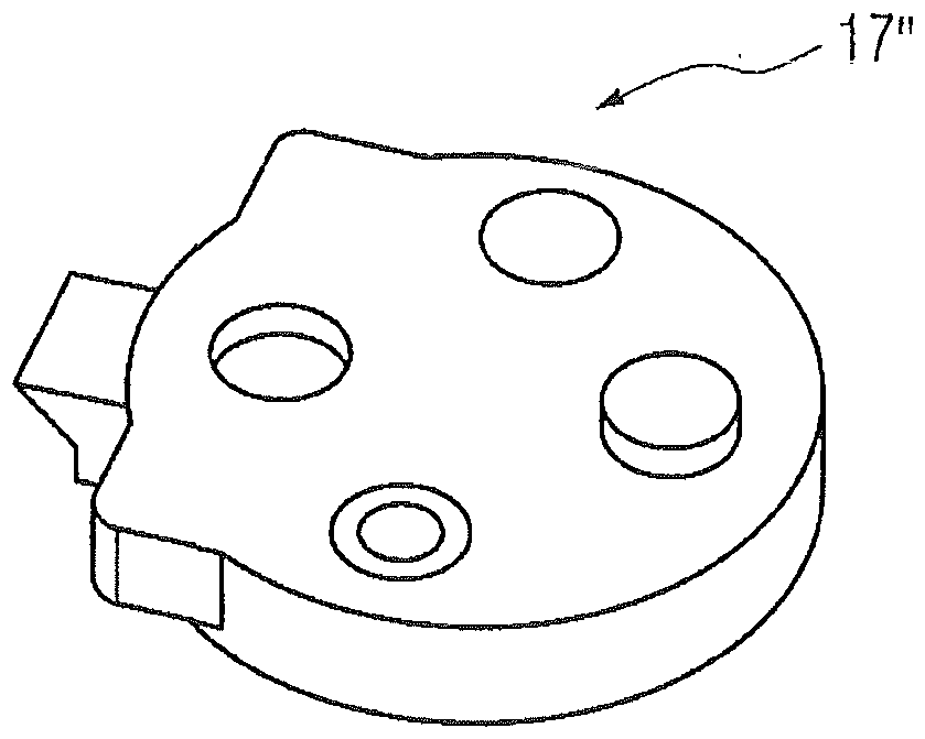
[0089] Figure 7 A three-dimensional representation of the seal ( 17 ) of the connecting mechanism ( 8 ) is shown. A seal (17) is used for a liquid-tight connection between the inner part (12) and the housing (13).
[0090] In a preferred embodiment (which is Figure 7a and b) are shown in a three-dimensional representation), the seal ( 17 ) consists of a first ( 17 ′) and a second half ( 17 ″), which are designed to correspond to each other, so that each half Each has a centering opening ( 18 ), a centering pin ( 19 ) and, in a particularly preferred embodiment, a valve seat ( 20 ) and a valve cover ( 21 ). The type of valve and the different possibilities with regard to the embodiment or the way of functioning are known from the prior art and are aimed in particular for use in a device for transferring liquid from a puncture bottle, for example in international application WO 2011/141200 A1 ( The contents of which are hereby recorded in the description) are described in detail and are therefore not further elaborated in this regard.
[0091] The seal (17) rotates together on the inner part (12) as the housing (13) rotates. Figure 8a : a schematic illustration showing the inner part ( 12 ) of the connecting mechanism ( 8 ) in the closed state with the installed seal ( 17 ), Figure 8b A schematic representation of the inner part ( 12 ) of the connecting mechanism ( 8 ) in the open state with the placed seal ( 17 ) is shown.
[0092] exist Figure 9 A view of the housing (13) with the hose coupling end (16) is shown schematically in . Ideally, the housing ( 13 ) has a defined coupling profile ( 30 ) at the hose coupling end ( 16 ) in a particular embodiment, so that the fluid flowing in or out through the connecting means ( 8 ) is of the type and the manner in which it is guided, ie the coupling of the double-lumen hose can take place independently of its angular position.
[0093] Figure 11a -d shows a three-dimensional representation of the device ( 2 ) according to the invention in operation.
[0094] Before the device (2) according to the invention is put into operation, the connecting means (8), to which the fluid line or container is connected, are put into the integrated first fixing element (4). Turn the disc (6). The connecting mechanism ( 8 ) is fixed in the vertical direction by the undercut of the rotating disk ( 6 ′) and in the horizontal direction by the latching lugs ( 6 ″).
[0095] Figure 11a The device ( 2 ) according to the invention with the inserted connection mechanism ( 8 ) and the commercially available piercing bottle ( 1 ) before insertion is shown.
[0096] A commercially available puncture bottle (1) consists of a body (1'), a neck (1'') and a head (1'''). The head (1"') contains a closure which can be configured as a plug or diaphragm and is fixed at the neck (1") by means of a rim.
[0097] A puncture bottle (1) is inserted into the device (2) according to the invention, wherein the puncture bottle (1) is pushed with the neck (1") into the second holder (5) as follows: The head (1"') of the puncture bottle (1) is directly opposite to the connecting mechanism (8). This is by Figure 11b can be seen.
[0098] Movement from the first ( 34 ) into the second position ( 35 ) by the actuating means ( 7 ), which is in connection with the lifting rod ( 9 ) of the device ( 2 ) according to the invention, as in Figure 11c The piercing bottle ( 1 ) is moved along the axis X towards the connecting mechanism ( 8 ) as shown in . In this case, the septum of the piercing bottle ( 1 ) is pierced by the piercing device ( 14 ) which, in the second position ( 34 ) of the actuating device ( 7 ), penetrates completely into the piercing bottle ( 1 ), so that the first A (14') and a second (14") line path leads into the inner space of the puncture bottle (1).
[0099] Figure 11d The opening of the connecting mechanism (8) by rotation of the housing (13) about the inner part (12) is shown. The rotation is preferably carried out at 90° with respect to one side of the device (2) according to the invention. Said rotating disk (6) is secured by locking the connecting means (8) via the housing (13) into the undercuts (6') and latching noses (6") of the rotating disk (6). Move together when the housing (13) rotates. The inner part ( 12 ) is docked at the second fixing element ( 5 ) or forms a positive fit therewith and is thereby fixed in the initial position of the inner part ( 12 ).
[0100] The rotation of the rotary disk ( 6 ) leads to two situations: on the one hand, the removal of the open connecting means ( 8 ) is reliably prevented and on the other hand, the connecting means ( 8 ) are fixed in its vertical position.
[0101] The connecting means ( 8 ) are closed again by the rotation of the housing ( 13 ) about the inner part ( 12 ) back into the central initial position of the housing ( 13 ). The rotary disk ( 6 ) is likewise rotated back into the initial position of the rotary disk ( 6 ) in synchronization with the housing ( 13 ).
[0102] If the transfer of the contents of the piercing bottle ( 1 ) is to be completed, the actuating device ( 7 ) is moved back from the second ( 35 ) into the first position ( 34 ). The lifting rod ( 9 ) of the device ( 2 ) according to the invention, at which the second fixing element ( 5 ) is fixed, moves together and separates the piercing bottle ( 1 ) and the connecting mechanism ( 8 ) from each other . The two parts can now be removed.
[0103] In another embodiment, it is conceivable that the piercing bottle ( 1 ) and the connecting device ( 8 ) are removed in the connected state if the connecting device ( 8 ) is closed. In this way, a quicker and more comfortable disassembly of the device ( 2 ) according to the invention after application can be achieved.
[0104] The insertion of the piercing bottle (1) and the connecting mechanism (8) into the device (2) according to the invention, the combination of all components by activating the actuating means (7) and the opening or closing of the connecting mechanism (8) can be done with one hand conduct.
[0105] exist Figure 12a A device according to the invention with a disconnected puncture bottle ( 1 ) and a closed connection ( 8 ) is shown in longitudinal section. If the actuating device ( 7 ) is in its first position ( 34 ), the adjusting element ( 10 ) fixes the rotary disk ( 6 ). Unintentional rotation of the rotary disk ( 6 ) and thus of the housing ( 13 ) of the connection mechanism ( 8 ) is prevented.
[0106] exist Figure 12b A device according to the invention with a connected puncture bottle and an open connection ( 8 ) is shown in longitudinal section. If the actuating means ( 7 ) is in its second position ( 35 ), the adjusting element ( 10 ) fixes the lifting rod ( 9 ). In this way, the piercing bottle (1) and the connecting mechanism (8) are prevented from being unintentionally guided away from each other.
[0107] The adjustment element thus supports a firm, reliable and precise fixation of the piercing bottle and the connecting means.
[0108] Figure 13a -c shows the mechanical mechanism of the device according to the invention during the connection of the piercing bottle in section in the individual steps.
[0109] Inside the device ( 2 ) according to the invention there is a mechanical transmission, for example in the form of a crank lever ( 11 ) or a gear, which is used for force transmission. The force to be used by the person for the combination of the piercing bottle ( 1 ) and the connecting device ( 8 ) is thereby greatly reduced, that is to say in individual cases up to 50 N, and the handling is facilitated.
[0110] Figure 14 A sensor ( 31 ), eg a Hall sensor, is shown in part of the device ( 2 ) according to the invention, which sensor ( 31 ) detects the position of the connecting means ( 8 ) by means of a magnet ( 33 ). In a special embodiment, the device according to the invention has an evaluation unit ( 32 ) as an external add-on device or integrated into the dialysis apparatus, which evaluation unit ( 32 ) detects the puncture bottle ( 31 ) by means of at least one sensor ( 31 ). 1) and/or the position of the connecting means (8) and/or the opening of the connecting means (8) and can give feedback to the dialysis machine or the user if required.
[0111] However, it is also conceivable to allow glimpses on the inner part (12) depending on the position of the housing (13) when rotating around the inner part (12) by means of a window in the housing of the connecting means (8) visual markings, such as colors or logos) to show whether the connecting mechanism (8) is open or closed.