Quick changing mechanism of operation robot for minimally invasive surgery

A technique for surgical robots and minimally invasive surgery, which is applied in surgical robots, surgical instruments, surgery, etc., and can solve problems such as scattered structural layout and large dimensions

Pending Publication Date: 2017-05-31
SHANDONG UNIV QILU HOSPITAL
View PDF4 Cites 9 Cited by
  • Summary
  • Abstract
  • Description
  • Claims
  • Application Information

AI Technical Summary

Problems solved by technology

The two existing commercial minimally invasive surgical robots are four-degree-of-freedom surgical tool systems driven by wires. However, these surgical tool systems still have shortcomings such as scattered structure layout and large external dimensions. Development potential

Method used


Image

  • Quick changing mechanism of operation robot for minimally invasive surgery
  • Quick changing mechanism of operation robot for minimally invasive surgery
  • Quick changing mechanism of operation robot for minimally invasive surgery

Examples


Embodiment 1

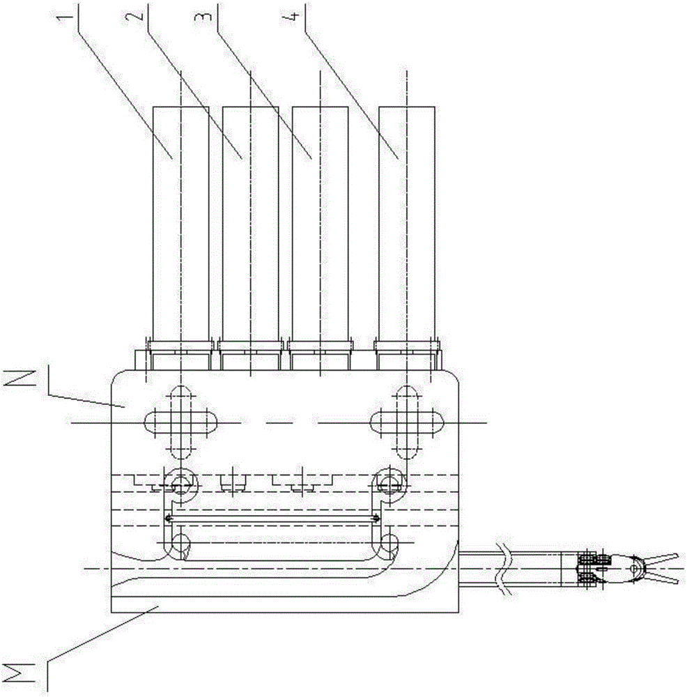
[0066] combine Figure 3 ~ Figure 6 To illustrate this embodiment, the quick change mechanism N consists of a left finger drive mechanism 1, a wrist joint drive mechanism 2, a right finger drive mechanism 3, an operation tube drive mechanism 4, an interface base, a connector 7, a connector 8 and a locking mechanism 9 and so on.

[0067] The left finger driving mechanism 1 consists of a large sun gear 1-1, a small sun gear 1-2, a planetary gear 1-3, a planet carrier 1-4, a sun gear shaft 1-5, an interface clutch disc 1-6, and a bearing 1- 7. Composed of bearings 1-8, couplings 1-9 and motors 1-10. The motor 1-10 is fixedly connected to the connector 7, the output shaft of the motor 1-10 is fixedly connected to one end of the coupling 1-9, and the other end of the coupling 1-9 is connected to the The sun gear shaft 1-5 is fixedly connected; the inner and outer rings of the big sun gear 1-1 have gears, and the big sun gear 1-1 is set on the sun gear shaft 1-5 and maintains a ra...

Embodiment 2

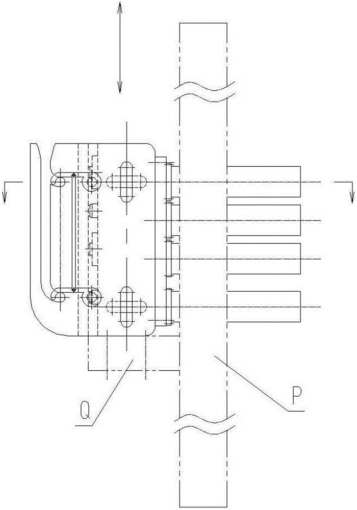
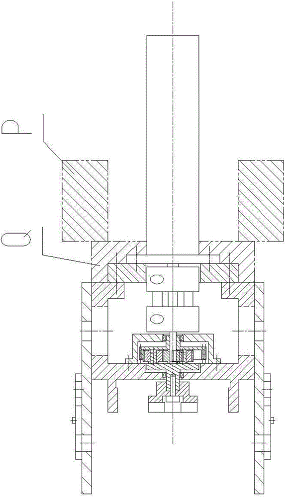
[0096] combine Figure 22 To illustrate this embodiment, on the basis of the technical solution of Embodiment 1, the locking mechanism of the quick change mechanism N can be changed to an additional Figure 12 The specific structure of the chute-type hook locking mechanism in is:

[0097] Two arc-shaped slots are respectively opened on each of the base covers 6, and the two ends of the locking hook 10 are hinged in the two arc-shaped chutes of the base cover 6. The axis of the locking hook 10 The direction is parallel to the end of the guide chute on the base cover 6 and the central connection line at the bottom of the middle groove, and the two ends of the locking hook 10 can slide in the two arc-shaped chute of the base cover 6, so There are two hooks on the locking hook 10, which are used to fix the two fixing pins on the actuator M of the surgical instrument.

[0098] When the surgical instrument actuator M is installed in the quick-change mechanism N, the surgical instr...


PUM


Abstract

The invention discloses a quick changing mechanism of an operation robot for minimally invasive surgery, comprising a left finger driving mechanism, a wrist joint driving mechanism, a right finger driving mechanism, an operation pipe driving mechanism and a base shell, a base cover, a connector and a locking mechanism. Through long bolt holes on the base cover and the base shell, relative installing position between the base cover and the base shell is adjusted; through a guide chute on a cutter base cover, relative installing position of an operation apparatus executing mechanism and an interface base is accurately positioned; a parallelogram hanging hook locking mechanism can exactly and conveniently lock and unlock the operation apparatus executing mechanism a decoupling mechanism is installed on the interface base, so as to simplify the structural design of the operation apparatus executing mechanism, and benefit the massive production of the operation apparatus executing mechanism. The quick changing mechanism of the operation robot for minimally invasive surgery is convenient to mount and dismount, easy to adjust, accurate in location, big in rigidity, reasonable in layout, miniaturization and light weight.

Description

technical field [0001] The invention relates to a medical device in the field of minimally invasive surgery, which can quickly replace different surgical instruments and provide multiple degrees of freedom for the surgical instruments in the process of minimally invasive surgical robot operations, especially relates to a suitable The quick-change mechanism of the minimally invasive surgical robot for minimally invasive surgical operations in the thoracic cavity and abdominal cavity. Background technique [0002] Minimally invasive surgery, represented by laparoscopy, is known as one of the important contributions of medical science to human civilization in the 20th century. Minimally invasive surgery refers to the use of long and thin surgical instruments to penetrate into the body through tiny incisions on the surface of the human body to perform surgery. operational. Compared with traditional open surgery, it has the advantages of small surgical incision, less bleeding, s...

Claims


Application Information

Patent Timeline
Patent Type & Authority Applications(China)
IPC IPC(8): A61B17/00A61B17/94A61B34/30
CPCA61B17/00234A61B2017/00464
Inventor 胡三元冯红光程晓林张光永田兆辉姜秀新
Owner SHANDONG UNIV QILU HOSPITAL
Why Eureka
Try Eureka