Coalescence principle-based oily-water separating device and method

A technology of oil-water separation device and water distribution device, applied in separation methods, immiscible liquid separation, liquid separation, etc., can solve the problems of single material in packing coalescence zone, no difference in surface free energy, complex structure, etc. Achieve the effect of increasing coalescence rate, improving oil-water separation efficiency, and low operating cost

Inactive Publication Date: 2017-05-31
SHANGHAI YOUHUA PROCESS INTEGRATED TECH CO LTD
View PDF7 Cites 10 Cited by
  • Summary
  • Abstract
  • Description
  • Claims
  • Application Information

AI Technical Summary

Problems solved by technology

[0008] Aiming at the problems existing in the existing oil-water separation device, such as complex structure, additional parts need to be provided, single material in the filler coalescing area, and no difference in surface free energy, the present invention provides an oil-water separation device and a separation method thereof

Method used


Image

  • Coalescence principle-based oily-water separating device and method

Examples


Embodiment 1

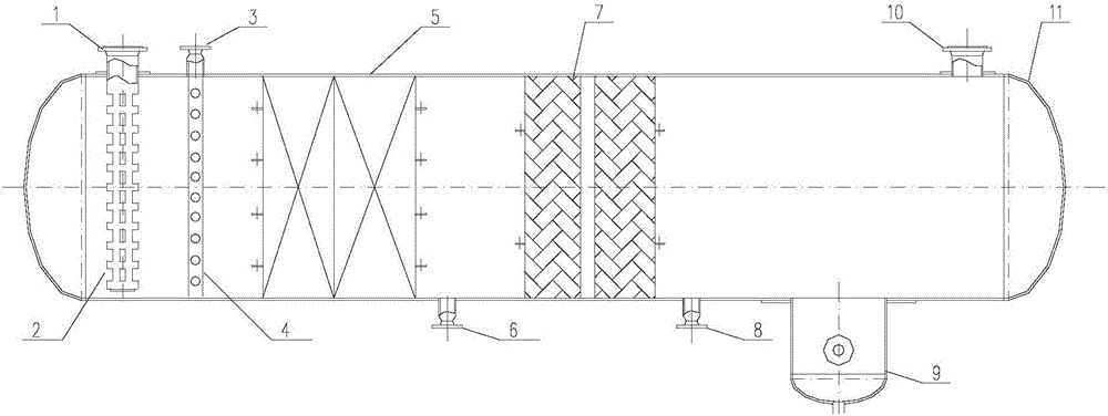
[0045] This embodiment provides an oil-water separation device, such as figure 1 As shown, the device is a horizontal structure, including a cylinder 11 and an interface. The top of the cylinder 11 is provided with a raw material liquid inlet 1, and the top of the cylinder 11 is provided with an oil phase outlet on the other side opposite to the raw material liquid inlet 1. 10; In the cylinder 11, a water distribution device 2, a corrugated plate coalescer 5 and a wire mesh coalescer 7 are arranged in sequence from the raw material liquid inlet 1 side; the water distribution device 2 is connected to the raw material liquid inlet 1, and the bottom of the cylinder 11 is There is a primary sewage outlet 6 between the corrugated plate coalescer 5 and the wire mesh coalescer 7, and the bottom of the cylinder 11 is provided with a water phase outlet 9 on the side opposite to the raw material liquid inlet 1. The bottom of the cylinder 11 is coalesced on the wire mesh A secondary sewag...

Embodiment 2

[0051] This embodiment provides an oil-water separation device. The device is a horizontal structure and includes a cylinder body and an interface 11. The top side of the cylinder body 11 is provided with a raw material liquid inlet 1, and the top of the cylinder body 11 is opposite to the raw material liquid inlet 1. The other side is provided with an oil phase outlet 10; in the cylinder 11, a corrugated plate coalescer 5 and a wire mesh coalescer 7 are arranged in sequence from the raw material liquid inlet 1 side; the bottom of the cylinder 11 is located at the corrugated plate coalescer 5 and silk Between the mesh coalescer 7 is provided a first-level sewage outlet 6, the bottom of the cylinder 11 is provided with a water phase outlet 9 on the side opposite to the raw material liquid inlet 1, and the bottom of the cylinder 11 is located between the wire mesh coalescer 7 and the water outlet 9 There is a secondary sewage outlet 8;

[0052] Wherein, the wire mesh coalescer 7 is...


PUM


Abstract

The present invention provides a coalescence principle-based oily-water separating device and method. The device is in a horizontal type structure, and comprises a barrel and a connector, wherein a raw material liquid inlet is formed in one side of the top of the barrel; an oil phase outlet is formed in the other side, opposite to the raw material liquid inlet, of the barrel; a corrugated plate coalescer and a screen mesh coalescer are arranged in the barrel from one side, in which the raw material liquid inlet is formed, of the barrel in sequence; a first-level drain outlet is formed in the bottom of the barrel, between the corrugated plate coalescer and the screen mesh coalescer; a water phase outlet is formed in one side, opposite to the raw material liquid inlet, of the bottom of the barrel; a second-level drain outlet is formed in the bottom of the barrel, between the screen mesh coalescer and the water phase outlet; the screen mesh coalescer is formed by weaving at least two materials with different surface free energy. In the present invention, by improving the screen mesh coalescer, the coalescence rate of oily-water drops can be increased during a capturing process, and further the oily-water separating effectiveness is improved; at the same time, the device is simple in structure, small in size and low in operation cost.

Description

Technical field [0001] The invention belongs to the technical field of liquid separation, and relates to an oil-water separation device and a separation method thereof, in particular to a high-efficiency oil-water separation device and a separation method based on the coalescence principle. Background technique [0002] There are a large number of oil-water separation processes in the petrochemical industry. With the deep exploitation of petroleum, the large-scale development of chemical enterprises and the strict requirements for environmental protection, oil-water separation technology has received increasing attention. At present, the physical technology of oil-water separation mainly includes gravity sedimentation, cyclone separation, coalescence separation, membrane separation, air flotation and other methods. [0003] The traditional oil-water separation process uses a combination of two-phase separators, large tank sedimentation and electrical desorption equipment, but the e...

Claims


Application Information

Patent Timeline
Patent Type & Authority Applications(China)
IPC IPC(8): B01D17/04B01D17/02
CPCB01D17/02B01D17/045
Inventor 孙虎良马素娟余金森屈娇燕崔明海
Owner SHANGHAI YOUHUA PROCESS INTEGRATED TECH CO LTD
Why Eureka
Try Eureka