
A method for automatically positioning the material surface to the laser focus

An automatic positioning and laser technology, which is applied in the direction of laser welding equipment, metal processing equipment, welding equipment, etc., can solve the problems of large differences between plasma bright spots and material surface brightness, unfavorable automatic operation of equipment, and inability to achieve one-time placement, etc., to achieve The effect of easy automation process, high degree of automation and high positioning accuracy

Active Publication Date: 2019-03-26
湖南景锐光电科技有限公司
View PDF6 Cites 0 Cited by
  • Summary
  • Abstract
  • Description
  • Claims
  • Application Information

AI Technical Summary

Problems solved by technology

This method can also be automated, but usually the brightness difference between the plasma bright spot and the material surface is large, which is not conducive to image processing, and even taking additional lighting measures as described in the document will require different lighting methods due to different material surface states and light intensity, which are not conducive to the automatic operation of the equipment
In addition, focusing can also be achieved by observing the size of the laser spot reflected by the surface of the material. Specifically, when the focus spot is observed to be the smallest, it is considered that the focus is completed. This method requires high optical path calibration, and there is also a need to control the material during the focusing process. The process of repeatedly moving and optimizing the surface before and after the focus cannot be achieved at one time, and it is more difficult to realize automatic control on this basis

Method used


Image

  • A method for automatically positioning the material surface to the laser focus
  • A method for automatically positioning the material surface to the laser focus
  • A method for automatically positioning the material surface to the laser focus

Examples


specific Embodiment approach

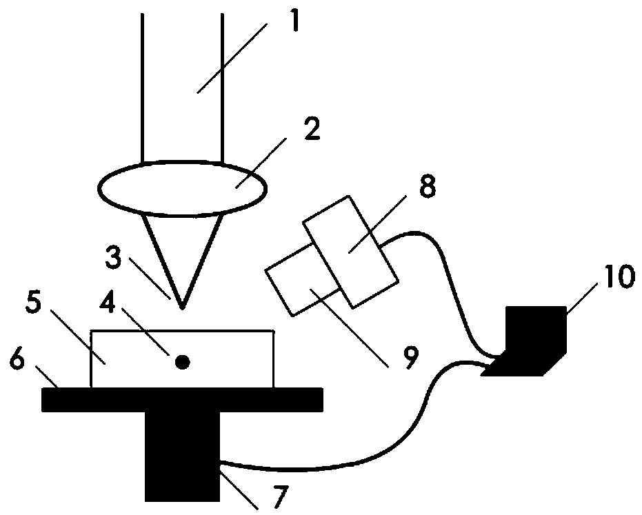
[0028] 1) Optical path construction: the method of the present invention is applicable to such as figure 1 The laser focus automatic positioning system shown includes laser beam 1, focusing lens 2, material to be processed 5, material fixture 6, electric translation stage 7, optical camera 8, microscope lens 9, control computer 10, and material to be processed 5 is clamped on On the material fixture 6, the surface of the processed material 5 faces the laser beam 1 focused by the focusing lens 2, the material fixture 6 and the material to be processed 5 are installed on the electric translation platform 7, and the optical camera 8 and the electric translation platform 7 are connected to the control computer 10 and controlled by the control program installed on the control computer 10, the control program mainly includes optical camera 8 image acquisition and processing functions and electric translation stage 7 in the direction of the optical axis to move back and forth control ...


PUM


Abstract

The invention relates to a method for automatically positioning the surface of a to-be-processed material to a laser focus and belongs to the technical field of laser processing. The method is based on the mirror surface imaging principle and the optical image measurement technology, the distance between the surface of the material and the center of a laser focus region is accurately calculated, and the surface of the material is automatically controlled to be accurately positioned to the center of the laser focus region. The method for automatically positioning the surface of the to-be-processed material to the laser focus has the advantages that full-automatic operation is achieved, the image processing target is simple and easy to achieved, the positioning accuracy is high, and the material cannot be damaged by lasers in the positioning stage.

Description

technical field [0001] The invention relates to a method for automatically positioning the surface of a material to be processed to a laser focus, and belongs to the technical field of laser processing. Background technique [0002] Laser processing has become one of the main methods of material processing. During the processing, the material usually needs to be positioned at the laser focus position, because the laser spot at the focus has the smallest light intensity and the largest. Positioning the material at the focal point increases processing accuracy while maximizing the use of laser energy. The laser focus usually mentioned refers to the point with the smallest cross-sectional area of ​​the beam in the direction of beam propagation, and according to the principle of optics, the focus point is a three-dimensional area in which the diameter of the spot changes most smoothly along the direction of beam propagation. This increases the difficulty of precise focusing, an...

Claims


Application Information

Patent Timeline
Patent Type & Authority Patents(China)
IPC IPC(8): B23K26/00B23K26/60B23K26/70
CPCB23K26/00B23K26/60B23K26/70
Inventor 朱志武
Owner 湖南景锐光电科技有限公司
Learn More