Energy balance system and method for power batteries

A technology of energy balance and power battery, which is applied in the direction of battery/fuel cell control devices, electric vehicles, vehicle energy storage, etc. It can solve the problems of large energy loss, low balance stability, and increased system redundancy, so as to avoid slow response , Speed ​​up the processing speed and overcome the effect of system redundancy

Inactive Publication Date: 2017-05-31
ZHONGJU HANGZHOU NEW ENERGY TECH CO LTD
View PDF4 Cites 4 Cited by
  • Summary
  • Abstract
  • Description
  • Claims
  • Application Information

AI Technical Summary

Problems solved by technology

[0007] The technical problem to be solved by the present invention is to overcome the defects of large energy loss, low balance stability, and increased system redundancy when u

Method used


Image

  • Energy balance system and method for power batteries
  • Energy balance system and method for power batteries
  • Energy balance system and method for power batteries

Examples


Embodiment 1

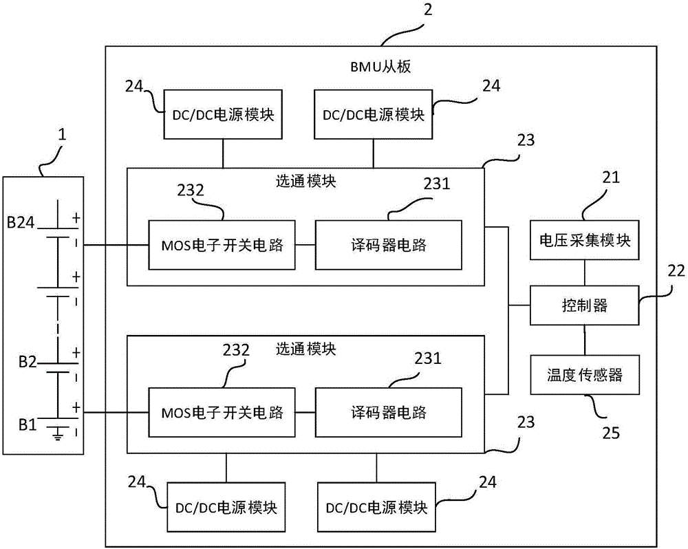
[0036] This embodiment provides an energy balance system for a power battery, such as figure 1 As shown, a battery pack 1 and a BMU slave board 2 are included, and the BMU slave board 2 includes a voltage acquisition module 21 and a controller 22 electrically connected to the voltage acquisition module;

[0037] Described BMU is provided with at least two gating modules 23 from the board, and each gating module includes a decoder circuit 231 and a MOS tube electronic switch circuit 232, and the decoder circuit 231 is connected with a photoelectric isolator. The MOS tube electronic switch circuit is electrically connected, and gate isolation can be realized through a photoelectric isolator.

[0038] The MOS tube electronic switch circuit 232 is electrically connected to the battery pack 1;

[0039] The BMU is also provided with at least four DC / DC power supply modules 24 from the board, and each gate module 23 is electrically connected with at least two of the DC / DC power supp...

Embodiment 2

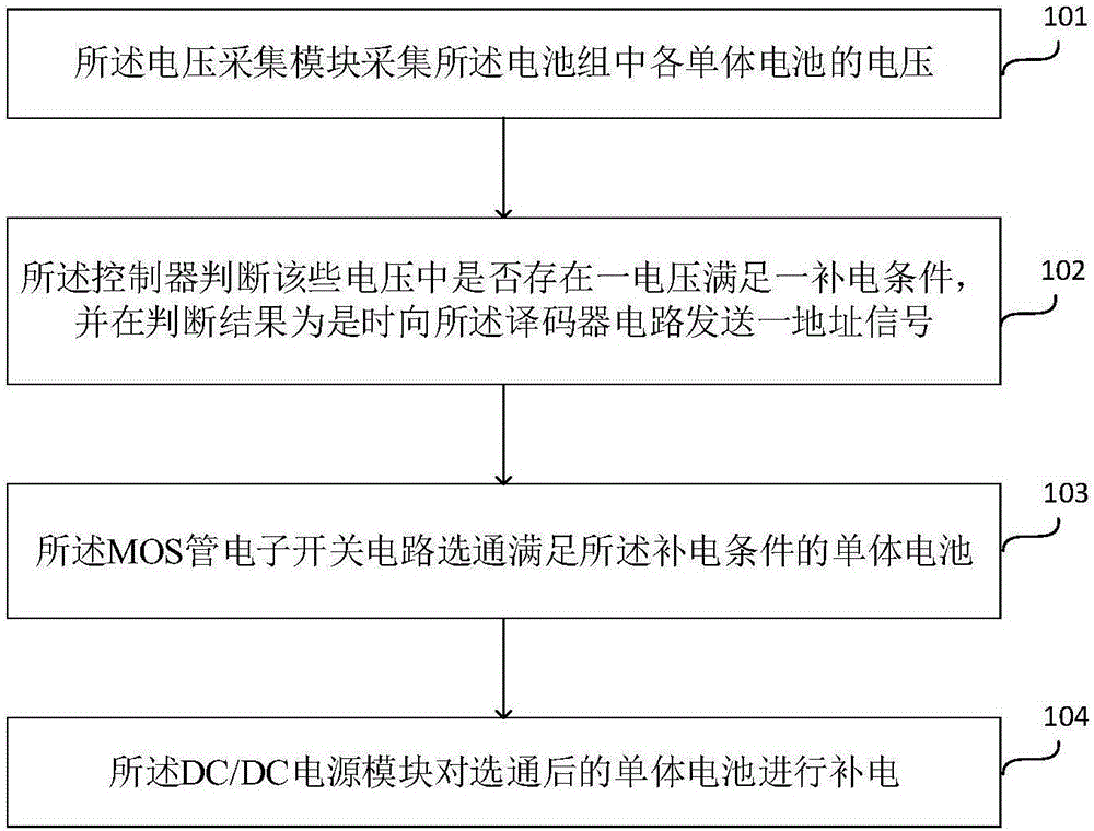
[0052] This embodiment provides an energy balance method for a power battery, such as image 3 As shown, it utilizes the energy balance system described in embodiment 1 to realize, including:

[0053] Step 101, the voltage collection module collects the voltage of each single battery in the battery pack;

[0054] Step 102, the controller judges whether there is a voltage among the voltages that satisfies a power supply condition, and sends an address signal to the decoder circuit when the judgment result is yes, and the address signal is used to indicate that the The address of the single battery that states the charging conditions;

[0055] Step 103, the MOS tube electronic switch circuit gates the single battery that satisfies the power supply condition;

[0056] Step 104, the DC / DC power supply module supplements power to the selected single battery.

[0057] Wherein, the charging condition includes: after the charging of the battery pack is completed, there is at least ...


PUM


Abstract

The invention discloses an energy balance system and method for power batteries. The system comprises a battery pack and a BMU slave panel. The BMU slave panel comprises a voltage acquisition module and a controller. Two or more gating modules are arranged on the BMU slave panel. Each gating module comprises a decoder circuit and a MOS pipe electronic switch circuit. The MOS pipe electronic switch circuits are electrically connected with the battery pack. Four or more DC/DC power source modules are further arranged on the BMU slave panel. Each gating module is electrically connected with the two or more DC/DC power source modules. The voltage acquisition module is used for acquiring voltages of single batteries in the battery pack. The controller is used for sending address signals to the decoder circuit when one of the voltages meets a charging condition. The MOS pipe electronic switch circuits are used for gating the single batteries meeting the charging condition. The scheme has the effects of being high in equilibrium stability, free from electromagnetic interference, little in energy loss, high in charging efficiency, fast in processing speed and high in precision.

Description

technical field [0001] The invention relates to the field of electronic technology and new energy vehicle power battery management system, in particular to an energy balancing system and method for power batteries. Background technique [0002] Due to the non-renewable and environmental pollution characteristics of petroleum energy, green new energy has been widely used. Vehicle exhaust has a devastating impact on global air quality, so electric vehicles are widely used in people's lives due to their advantages of energy saving and environmental protection. With the development of lithium-ion battery technology, lithium-ion batteries are increasingly being used in the field of electric vehicles. The most important difference between electric vehicles and traditional fuel vehicles is that power batteries replace traditional fuel as a power source. Therefore, the safety and efficiency of power lithium-ion batteries have become an important development technology for electric...

Claims


Application Information

Patent Timeline
IPC IPC(8): B60L11/18
CPCB60L58/22B60L2240/545B60L2240/547Y02T10/70
Inventor 赵政威潘成赣张新锋梁铨
Owner ZHONGJU HANGZHOU NEW ENERGY TECH CO LTD
Why Eureka
Try Eureka