Suspension frame carrying arm structure of middle-low-speed magnetic suspension vehicle

A suspension frame and support arm technology, which is applied to vehicle components, electric vehicles, electric traction, etc., can solve problems such as high manufacturing precision requirements, insufficient structural stability, and large intervals between adjacent motors, so as to reduce maintenance costs and weaken the terminal. The effect of the internal effect and the elimination of welding deformation

Active Publication Date: 2017-05-31
SOUTHWEST JIAOTONG UNIV
View PDF7 Cites 5 Cited by
  • Summary
  • Abstract
  • Description
  • Claims
  • Application Information

AI Technical Summary

Problems solved by technology

[0004] The invention provides a support arm structure for a suspension frame of a medium-low speed maglev vehicle, which can effectively solve the existing support arm structures with high manufacturing precision requirements, insufficient structural stability, inconvenient disassembly and assembly of motors, limited length of motors and problems of adjacent motors. Problems such as large intervals

Method used


Image

  • Suspension frame carrying arm structure of middle-low-speed magnetic suspension vehicle
  • Suspension frame carrying arm structure of middle-low-speed magnetic suspension vehicle
  • Suspension frame carrying arm structure of middle-low-speed magnetic suspension vehicle

Examples


Embodiment approach 1

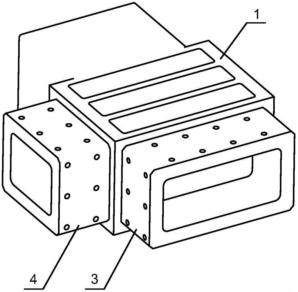
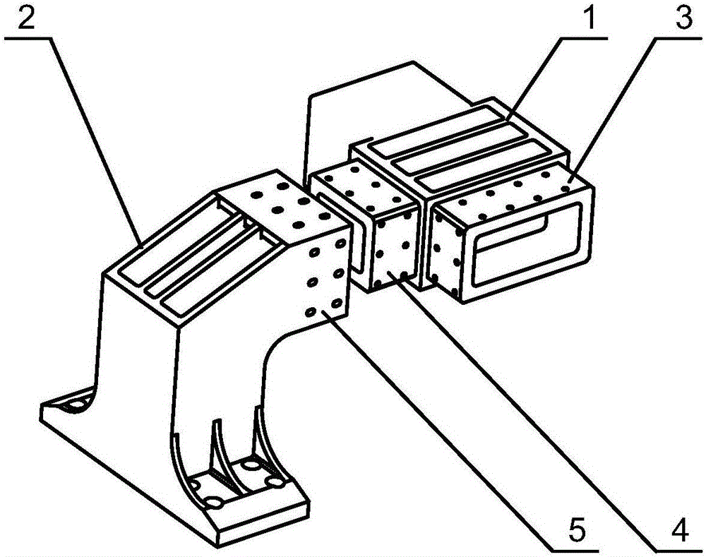
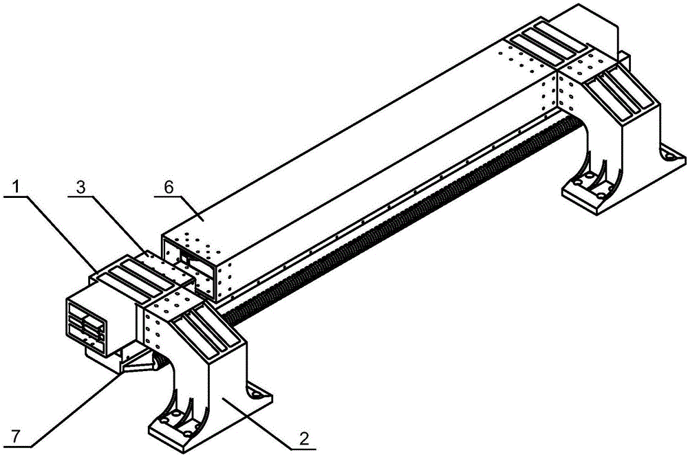
[0019] Embodiment 1, such as figure 1 As shown, a support arm structure for the suspension frame of a medium-low speed maglev vehicle, its main function is to provide the installation foundation for the suspension electromagnet, and the suspension electromagnet is attracted to the track to make the vehicle suspend. The support arm structure of the low-speed maglev vehicle suspension frame mainly includes the support arm upper part 1 and the support arm lower part 2. The mortise and holes of the parts are fitted through tenon joints and fastened with bolts. The upper part 1 of the bracket arm is provided with a first boss structure 4 as a tenon on the side close to the second boss structure 3, and the upper part 1 of the bracket arm and the mortise hole of the horizontal end 5 of the lower part 2 of the bracket arm are fitted through tenon joints and tightened with bolts. solid.

[0020] Such as figure 2 , 3 As shown, the upper part 1 of the support arm is provided with a ...


PUM


Abstract

The invention provides a suspension frame carrying arm structure of a middle-low-speed magnetic suspension vehicle, and relates to the technical field of magnetic suspension vehicle travelling mechanisms. The suspension frame carrying arm structure comprises an upper carrying arm portion, a lower carrying arm portion and a longitudinal beam connected with a carrying arm. The upper carrying arm portion and the lower carrying arm portion are in joggle joint through a tenon and a mortise, and are fastened through a bolt; the upper carrying arm portion and the longitudinal beam are in joggle joint through a tenon and a mortise, and are fastened through a bolt. Each tenon is of a hollow structure in the shape of double-hollow square blocks, and two rows of screw holes are distributed evenly in each of four surfaces. The lower carrying arm portion is an 'r-shaped' structure with a mounting base, the horizontal end of the 'r-shaped' structure is a mortise matched with a first boss structure, and two rows of screw holes are distributed evenly in each of four surfaces of the 'r-shaped' structure. A mounting base is arranged at the vertical end of the 'r-shaped' structure. A bevel with ridges is arranged at the right-angle position of the 'r-shaped' structure. Other two embodiments can be derived on the basis of the joggle-joint structures. The suspension frame carrying arm structure is mainly applied to suspension frame carrying arms of middle-low-speed magnetic suspension vehicles.

Description

technical field [0001] The invention belongs to the technical field of the traveling mechanism of a conventional electromagnetic levitation type maglev vehicle, and in particular relates to a suspension frame structure of a medium-low speed maglev vehicle. Background technique [0002] There is a significant difference between the conventional electromagnetic suspension (EMS) maglev vehicle system and the ordinary rail vehicle system, which is mainly reflected in that compared with the bogie of the traditional rail vehicle, the maglev vehicle uses a suspension frame to support the car body. The suspension frame has no wheel set structure, but uses the suction and repulsion between the suspension electromagnet and the track to make the vehicle suspend and walk. Its advantage is that it replaces the wheel-rail contact with suspension, which greatly reduces the wear and tear during the operation of the vehicle and reduces the operating cost of the vehicle. At the same time, th...

Claims


Application Information

Patent Timeline
Patent Type & Authority Applications(China)
IPC IPC(8): B60L13/04
CPCB60L13/04
Inventor 马卫华高唱谢钦罗世辉
Owner SOUTHWEST JIAOTONG UNIV
Why Eureka
Try Eureka