Distributed propulsion system

A propulsion system and distributed technology, applied in the field of aviation propulsion systems, can solve problems such as unfavorable aircraft layout, heavy weight, complex mechanical transmission mechanism, etc., and achieve the effect of improving realizability, large bypass ratio, and high system efficiency

Active Publication Date: 2017-05-31
西安觉天动力科技有限责任公司
View PDF12 Cites 13 Cited by
  • Summary
  • Abstract
  • Description
  • Claims
  • Application Information

AI Technical Summary

Problems solved by technology

[0010]In order to overcome the existing energy storage equipment and motor power that cannot meet the demand based on power distribution in the prior art; when based on mechanical transmission,

Method used


Image

  • Distributed propulsion system
  • Distributed propulsion system
  • Distributed propulsion system

Examples


Embodiment 1

[0049] This embodiment is a distributed propulsion system based on working medium transmission.

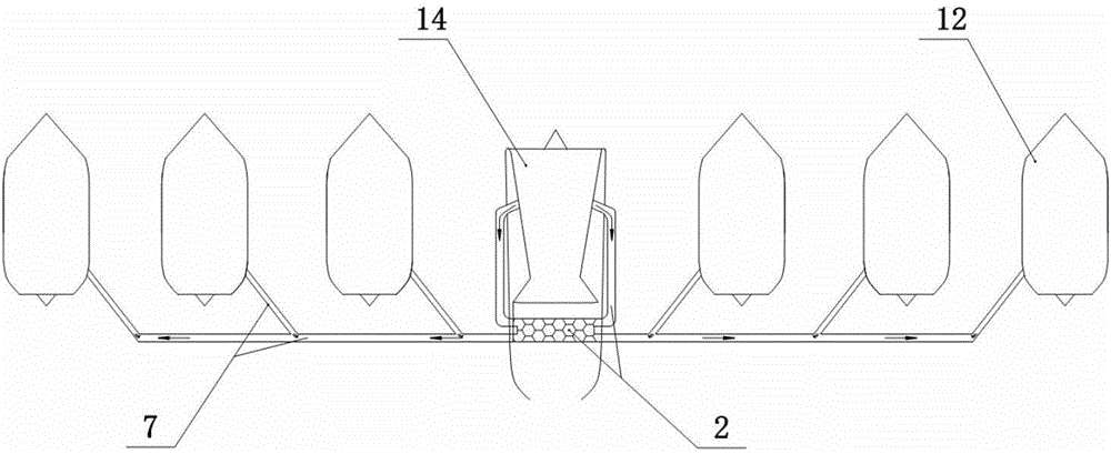
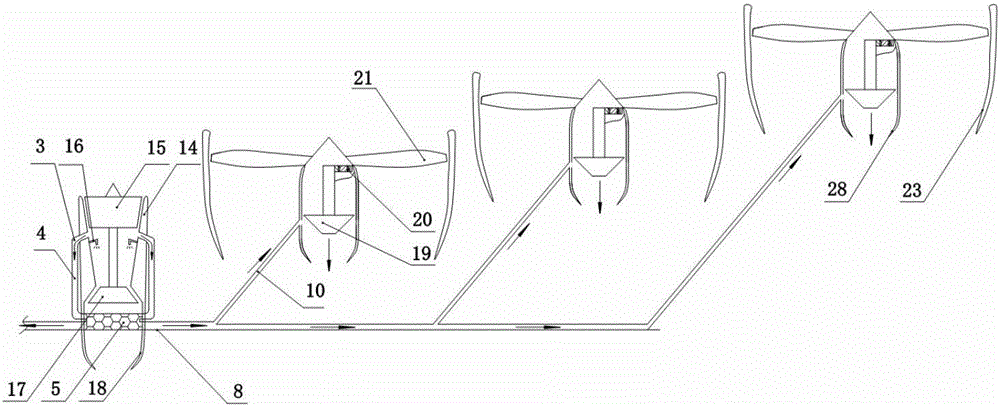
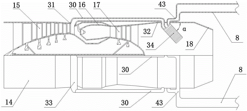
[0050] This embodiment includes a turbine engine core machine 14 , a high-efficiency working medium transmission device 7 , a high-energy working medium collection device 2 and a distributed propeller 12 . The input end of the gas collection device 3 of the high-energy working medium collection device 2 communicates with the output end of the core machine compressor 15 of the turbine engine core machine; the output end of the high-energy working medium collection device 2 communicates with the high-efficiency working medium transmission device 7 import connections. The output end of the transmission branch pipe 10 in the high-efficiency working medium transmission device 7 communicates with the input end of the propeller turbine volute 45 of each distributed propeller 12 respectively; The transfer manifold 8 in the device 7 communicates. In this embodiment, there are six distrib...

Embodiment 2

[0070] This embodiment is a distributed propulsion system based on working medium transmission.

[0071] Embodiment 2 differs from Embodiment 1 in that the gas turbine engine core machine 14 in Embodiment 2 is a twin-rotor turbojet engine. All the other parts are the same as in Example 1.

[0072] This embodiment includes a turbine engine core machine 14 , a high-efficiency working medium transmission device 7 , a high-energy working medium collection device 2 and a distributed propeller 12 . The input end of the gas collection device 3 of the high-energy working medium collection device 2 communicates with the output end of the high-pressure compressor 6 of the turbine engine core machine; connected. The output end of the transmission branch pipe 10 in the high-efficiency working medium transmission device 7 communicates with the input end of the propeller turbine volute 45 of each distributed propeller 12 respectively; The transfer manifold 8 in the device 7 communicates....

Embodiment 3

[0076] This embodiment is a distributed propulsion system based on working medium transmission.

[0077] The difference between embodiment 3 and embodiment 1 is that the fan 21 in embodiment 1 is replaced by propeller 22 in embodiment 3. All the other parts are the same as in Example 1.

[0078] This embodiment includes a turbine engine core machine 14 , a high-efficiency working medium transmission device 7 , a high-energy working medium collection device 2 and a distributed propeller 12 . The input end of the gas collection device 3 of the high-energy working medium collection device 2 communicates with the output end of the high-pressure compressor 6 of the turbine engine core machine; connected. The output end of the transmission branch pipe 10 in the high-efficiency working medium transmission device 7 communicates with the input end of the propeller turbine volute 45 of each distributed propeller 12 respectively; The transfer manifold 8 in the device 7 communicates. ...


PUM


Abstract

The invention discloses a distributed propulsion system. The distributed propulsion system is characterized in that input ends of gas collecting devices of a high-energy working medium collecting device are communicated with an output end of a core machine gas compressor of a turbine engine core machine; output ends of the high-energy working medium collecting device are communicated with inlets of efficient working medium transmission devices; output ends of transmission branched pipes of the efficient working medium transmission devices are respectively communicated with input ends of propeller turbine volute casings of various distributed propellers; input ends of the transmission branched pipes are communicated with transmission header pipes of the efficient working medium transmission devices; the six distributed propellers are uniformly distributed on two sides of the turbine engine core machine. The distributed propulsion system has the advantages that the shortcoming of dependence of distributed propulsion systems on the basis of electric power distribution on energy storage equipment with high energy density and super-power motors can be overcome, and the implementability of the distributed propulsion system can be enhanced; mechanical restraint between gas generators and propellers in a distributed propulsion system on the basis of mechanical transmission can be dispensed, bypass ratio limit on turbo fan engines and the traditional distributed power can be broken through, the distributed propulsion system is in a heat regenerative design, and the propulsion efficiency can be improved.

Description

technical field [0001] The invention relates to an aviation propulsion system, in particular to a distributed propulsion system. Background technique [0002] Economy is a key factor to be considered for transport aircraft. At the same time, as environmental problems continue to become prominent, people are also putting forward more and more stringent requirements for reducing carbon emissions. This all requires improving the efficiency of the existing transporter power (turbofan engine). One of the effective measures to improve turbofan engine efficiency is to use a higher bypass ratio to obtain high propulsion efficiency. The bypass ratio of the current civil turbofan engine is close to 10, but it is difficult to further improve it due to the limitation of structure and component matching. The distributed propulsion system breaks through the structural and component matching limitations of the traditional turbofan engine, so a higher bypass ratio can be obtained. At the...

Claims


Application Information

Patent Timeline
IPC IPC(8): B64G1/40
CPCB64G1/40
Inventor 陈玉春贾琳渊康瑞元张少锋赵博博
Owner 西安觉天动力科技有限责任公司
Why Eureka
Try Eureka