

A kind of silicon-based ceramic core and preparation method thereof
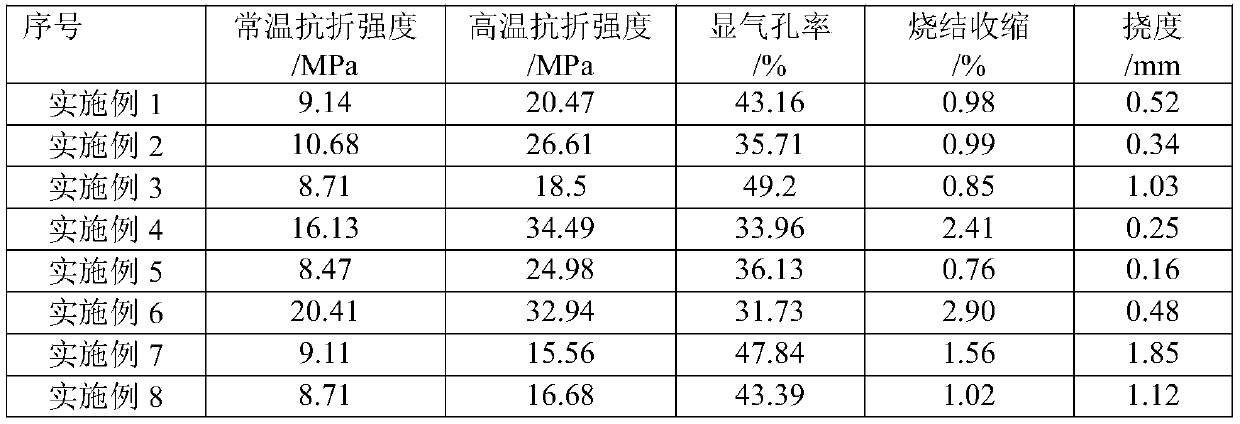
A ceramic core and silicon-based technology, applied in the field of silicon-based ceramic core and its preparation, can solve the problems of insufficient high-temperature strength and large high-temperature deflection of silicon-based ceramic cores
- Summary
- Abstract
- Description
- Claims
- Application Information
AI Technical Summary
Problems solved by technology
Method used
Image

Examples
Embodiment 1
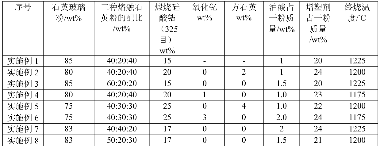
[0028] The formula of the core powder is shown in Table 1, which includes: mineralizer, quartz glass powder, surfactant, plasticizer, and additives.
[0029] Zirconium silicate is a mineralizer, wherein, zirconium silicate is calcined zirconium silicate of 325 mesh; dry powder is composed of quartz glass powder and mineralizer;
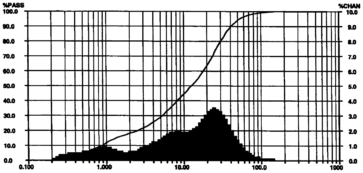
[0030] The quartz glass powder is obtained by mixing three kinds of fused silica powders of 240 mesh, 600 mesh and 1000 mesh.
[0031] Oleic acid is a surfactant;
[0032] The plasticizer is prepared from paraffin wax, beeswax and polyethylene, wherein the proportions of paraffin wax, beeswax and polyethylene in the plasticizer are 85%, 10% and 5%.
[0033] The raw materials were weighed according to the ratio in Table 1, and the silicon-based ceramic core was prepared as follows:
[0034] Dry mixing: Weigh the mineralizer, quartz powder glass powder, additives according to the predetermined ratio, put them into the mixer, mix the materials until th...
Embodiment 2
[0047] The formula of core powder is shown in Table 1.
[0048] The quartz glass powder is obtained by mixing three kinds of fused silica powders of 240 mesh, 600 mesh and 1000 mesh.
[0049] The plasticizer is prepared from paraffin wax, beeswax and polyethylene, wherein the proportions of paraffin wax, beeswax and polyethylene in the plasticizer are 85%, 10% and 5%.
[0050] Weigh the raw materials according to the above ratio, and prepare the silicon-based ceramic core according to the following method:
[0051] Dry mixing: Weigh the mineralizer, quartz powder glass powder, additives according to the predetermined ratio, put them into the mixer, mix the materials until the powder is fully mixed evenly, and dry at 103°C to constant weight after discharging to obtain the powder;
[0052]Configure plasticizer: weigh paraffin, beeswax and polyethylene according to a predetermined ratio, add it to a vacuum wax blender, heat until melted, stir evenly, continue to stir and vacuum...
Embodiment 3
[0061] The formula of core powder is shown in Table 1.
[0062] The quartz glass powder is obtained by mixing three kinds of fused silica powders of 240 mesh, 600 mesh and 1000 mesh.
[0063] The plasticizer is prepared from paraffin wax, beeswax and polyethylene, wherein the proportions of paraffin wax, beeswax and polyethylene in the plasticizer are 85%, 9% and 6%.
[0064] Weigh the raw materials according to the above ratio, and prepare the silicon-based ceramic core according to the following method:
[0065] Dry mixing: Weigh the mineralizer, quartz powder glass powder, additives according to the predetermined ratio, put them into the mixer, mix the materials until the powder is fully mixed evenly, and dry at 103°C to constant weight after discharging to obtain the powder;
[0066] Configure plasticizer: weigh paraffin, beeswax and polyethylene according to a predetermined ratio, add it to a vacuum wax blender, heat until melted, stir evenly, continue to stir and vacuum...
PUM
 Abstract
Description
Claims
Application Information