Root key construction method using root key construction device of root type pouring pile

A technology of construction device and construction method, applied in sheet pile wall, foundation structure engineering, construction and other directions, can solve problems such as high construction cost, slope restriction, hidden safety hazards, etc., and achieve the effect of improving construction efficiency

Active Publication Date: 2018-11-27
HUAIYIN INSTITUTE OF TECHNOLOGY
View PDF4 Cites 0 Cited by
  • Summary
  • Abstract
  • Description
  • Claims
  • Application Information

AI Technical Summary

Problems solved by technology

[0004] First, during the entire construction process, hoisting devices are required, resulting in very high construction costs
[0005] Second, the construction is carried out in the hoisting state. Although the suspension rod has been used instead of the suspension rope to improve a certain rigidity, there will still be shaking, which is a great safety hazard during the construction process.
[0006] Third, the part that pushes the root key into the side wall of the pile pit is a slope structure. When the slope structure acts on the root key, it will produce a vertical force at the same time, and push the root key into the side of the pile pit. When the wall is closed, the root key cannot be guaranteed to be jacked horizontally, and the construction quality of the root key cannot be guaranteed
[0007] Fourth, the number of root keys in the same layer is greatly affected by the number of slopes at each angle, and the volume occupied by the slopes is relatively large, resulting in a limited upper limit on the number of slopes
[0008] Fifth, due to the large mention of the slope surface and the need to bear a certain pressure, the weight of the slope surface is relatively large, which increases the load of hoisting, resulting in higher requirements for the load-bearing capacity of the crane required, which further increases the construction cost

Method used


Image

  • Root key construction method using root key construction device of root type pouring pile
  • Root key construction method using root key construction device of root type pouring pile
  • Root key construction method using root key construction device of root type pouring pile

Examples


Embodiment Construction

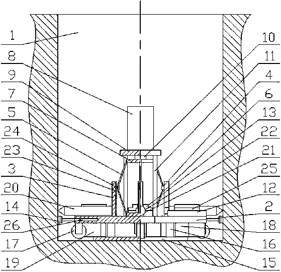
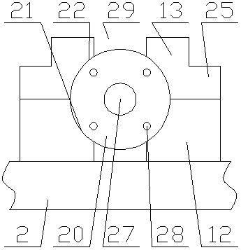
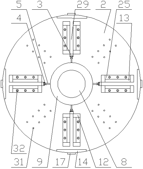
[0067] to combine Figure 1~Figure 6 As shown, the present invention includes a base plate 2, a hydraulic cylinder 8 is fixed above the center of the base plate 2, and the end of the hydraulic rod 10 of the hydraulic cylinder 8 protrudes downward toward the base plate 2, and the base plate 2 is located on the hydraulic cylinder There are many vertical push rods 3 evenly distributed around 8 (the present invention can have 8 vertical push rods 3 evenly distributed around the hydraulic cylinder 8 on the base plate 2 at most, and only 4 vertical push rods 3 are evenly distributed in this embodiment. type push rod 3), the hydraulic rod 10 is connected with the vertical push rod 3 through a linkage mechanism, so that the vertical push rod 3 moves along the radial direction of the base plate 2, and the edge of the upper surface of the base plate 2 corresponds to the vertical The push rods 3 are respectively provided with a root key limiting device, the root key limiting device makes...


PUM


Abstract

The invention discloses a rootkey construction method of a rootkey construction device utilizing a root type cast-in-place pile. A substrate is hoisted to the pit bottom, a hydraulic rod is made to downwards stretch out of a hydraulic cylinder, a pressing plate A is driven to downwards press towards one side of a pressing plate B, a connection rod A and a connection rod B outwards push a connection block and a vertical push plate, and the vertical push plate is made to horizontally jack rootkeys into the side wall of a pile pit; after the rootkeys are jacked into the side wall, the hydraulic rod is made to retreat to the hydraulic cylinder; operators position vertical racks and steel bars of the rootkeys, it is guaranteed that the vertical racks are straight, the vertical racks and the tail ends of the rootkeys are fixed, and the vertical racks are made to be meshed with corresponding transmission gears; and when all the rootkeys on a certain layer are fixedly provided with the vertical racks, drive motors are started to drive the transmission gears to climb upwards along the vertical racks. It is known through the above steps that by means of the rootkey construction method of the rootkey construction device utilizing the root type cast-in-place pile, all the rootkeys on the same layer can be constructed simultaneously, climbing in the pile pit can be performed automatically without depending on external force so as to complete construction of all the rootkeys in the pile pit, and construction efficiency of the rootkeys is improved.

Description

technical field [0001] The invention relates to the technical field of root pile construction, in particular to a root key construction method utilizing a root key construction device of a root type cast-in-place pile. Background technique [0002] In the field of construction, pile foundations are usually used for bearing pressure, and pile foundations bear pressure through the joint action of pile side resistance and pile end resistance. The bearing capacity of the pile foundation is related to the resistance provided by the pile side and pile end. By increasing the diameter of the pile foundation or the length of the pile foundation, that is, by increasing the stressed area, the pile side resistance or pile end resistance of the pile foundation can be improved. , thereby increasing the bearing capacity of the pile foundation. However, in actual construction, the longer the pile foundation is, the more difficult the construction is; the larger the diameter of the pile fou...

Claims


Application Information

Patent Timeline
Patent Type & Authority Patents(China)
IPC IPC(8): E02D5/48E02D5/34E02D13/00
CPCE02D5/34E02D5/48E02D13/00
Inventor 何春林龚成中董云相军
Owner HUAIYIN INSTITUTE OF TECHNOLOGY
Why Eureka
Try Eureka