Drill rod

A drill pipe and hollow rod technology, applied in drill pipe, drill pipe, drilling equipment, etc., can solve problems such as affecting construction quality and operation efficiency, screw blade wear, unstable drilling and mixing quality, etc.

Active Publication Date: 2017-05-31
SHANGHAI GUANGDA FOUND ENG
View PDF9 Cites 4 Cited by
  • Summary
  • Abstract
  • Description
  • Claims
  • Application Information

AI Technical Summary

Problems solved by technology

[0003] In the prior art, when using the SMW drilling rig to drill in cobblestone, gravel layers and other strata, the drill pipe composed of pure helical blades is generally used in conjunction with the special sandy soil d

Method used


Image

  • Drill rod
  • Drill rod

Examples


Embodiment 1

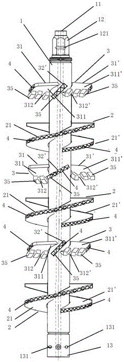
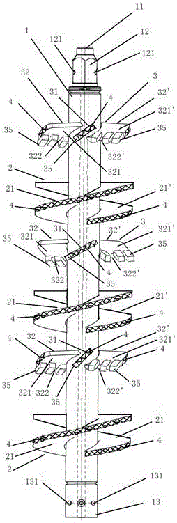
[0022] like figure 1 and 2 As shown, a drill pipe includes: a hollow rod body 1, including a grouting channel 11 arranged in the inner cavity of the hollow rod body 1, an outer hexagonal joint 12 and an inner hexagonal joint 13 located at the upper and lower ends of the hollow rod body 1; multiple sets of helical fins , each group of helical fins 2 includes double-headed helical fins 21, 21' arranged on the outer wall of the hollow rod body 1; multiple sets of cutting blades, each group of cutting blades 3 includes two first blades arranged on the outer wall of the hollow rod body 1 31, 31' and two second blades 32, 32'; and a wear plate 4; wherein, the outer hexagon joint 12 of the hollow rod body 1 is provided with two symmetrical outer hexagons perpendicular to its axial center There are two semicircular grooves 121 on the surface, and the inner hexagonal joint 13 is provided with two pin holes 131 perpendicular to its axial center and formed by passing through the outer w...

Embodiment 2

[0024] like figure 1 and 2 As shown, a drill pipe includes: a hollow rod body 1, including a grouting channel 11 arranged in the inner cavity of the hollow rod body 1, an outer hexagonal joint 12 and an inner hexagonal joint 13 located at the upper and lower ends of the hollow rod body 1; multiple sets of helical fins , each group of helical fins 2 includes double-headed helical fins 21, 21' arranged on the outer wall of the hollow rod body 1; multiple sets of cutting blades, each group of cutting blades 3 includes two first blades arranged on the outer wall of the hollow rod body 1 31, 31' and two second blades 32, 32'; and wear plate 4; wherein, the two symmetrical outer hexagonal surfaces of the outer hexagonal joint 12 of the hollow rod body 1 are provided with Two semi-circular grooves 121, two pin holes 131 which are perpendicular to its axial center and formed by passing through the outer wall of the inner hexagon joint and two symmetrical inner hexagon faces in the sa...

Embodiment 3

[0026] like figure 1 and 2 As shown, a drill pipe includes: a hollow rod body 1, including a grouting channel 11 arranged in the inner cavity of the hollow rod body 1, an outer hexagonal joint 12 and an inner hexagonal joint 13 located at the upper and lower ends of the hollow rod body 1; multiple sets of helical fins , each group of helical fins 2 includes double-headed helical fins 21, 21' arranged on the outer wall of the hollow rod body 1; multiple sets of cutting blades, each group of cutting blades 3 includes two first blades arranged on the outer wall of the hollow rod body 1 31, 31' and two second blades 32, 32'; and wear plate 4; wherein, the two symmetrical outer hexagonal surfaces of the outer hexagonal joint 12 of the hollow rod body 1 are provided with Two semi-circular grooves 121, two pin holes 131 which are perpendicular to its axial center and formed by passing through the outer wall of the inner hexagon joint and two symmetrical inner hexagon faces in the sa...


PUM


Abstract

A drill rod comprises a hollow rod body comprising an outer hexagonal joint and an inner hexagonal joint, a plurality of sets of spiral wings comprising dual-end spiral wings, a plurality of sets of cutting blades comprising two first blades and two second blades and wear-resisting plates; the outer hexagonal joint and the inner hexagonal joint are provided with a semicircular groove and a pin hole respectively; the multiple sets of spiral wings are arranged on the outer wall of the hollow rod body at equal intervals in a radial mode; the multiple sets of cutting blades are arranged on the outer wall of the hollow rod body at equal intervals, first blade faces of the first blades are arranged horizontally, and the first lower edges of the blades are blade edges inclined downwards; second blade faces of the second blades are arranged upwards and downwards, and the second lower edges of the second blades are blade edges inclined downwards; the first blades and the second blades are arranged at equal angle intervals in the radial direction of the hollow rod body; the wear-resisting plates are arranged on the dual-end spiral wings of the spiral wings and a free end arc face of the first and second blades of the cutting blades. The drill rod has the advantages that drilling and excavating are stable, stirring is uniform and the blades resist wear, and the drilling and excavating efficiency is improved.

Description

technical field [0001] The invention relates to a drill rod for agitating drilling rigs suitable for drilling and stirring pebble layers, gravel layers and other foundations, which can widely meet the requirements of underground continuous walls such as urban buildings, subway station shaft enclosures, dam seepage prevention treatment, and soft soil foundation reinforcement. Construction needs. Background technique [0002] In the construction of underground facilities of high-rise buildings, shaft enclosures of subway stations, anti-seepage treatment of river embankments, and reinforcement and improvement of soft soil foundations, the column-type soil cement wall construction method (ie, SMW construction method) has low construction noise and has no impact on the surrounding environment. Small, adjacent piles are completely lapped, good anti-seepage performance, environmental protection and energy saving, short construction period and good economy. Therefore, this construct...

Claims


Application Information

Patent Timeline
IPC IPC(8): E21B17/22E21B17/10E21B10/43
CPCE21B10/43E21B17/1085E21B17/22
Inventor 吴国明李星李俊谢兆良
Owner SHANGHAI GUANGDA FOUND ENG
Why Eureka
Try Eureka