Integrated tail gas aftertreatment system

A tail gas post-treatment and tail gas technology, which is applied in exhaust gas treatment, gas channels, exhaust devices, etc., to achieve the effect of improved mixing uniformity and efficient and low elimination of harmful components

Inactive Publication Date: 2017-05-31
ROBERT BOSCH GMBH
View PDF6 Cites 9 Cited by
  • Summary
  • Abstract
  • Description
  • Claims
  • Application Information

AI Technical Summary

Problems solved by technology

However, this layout still leaves a lot of room for compre

Method used


Image

  • Integrated tail gas aftertreatment system
  • Integrated tail gas aftertreatment system
  • Integrated tail gas aftertreatment system

Examples


Embodiment Construction

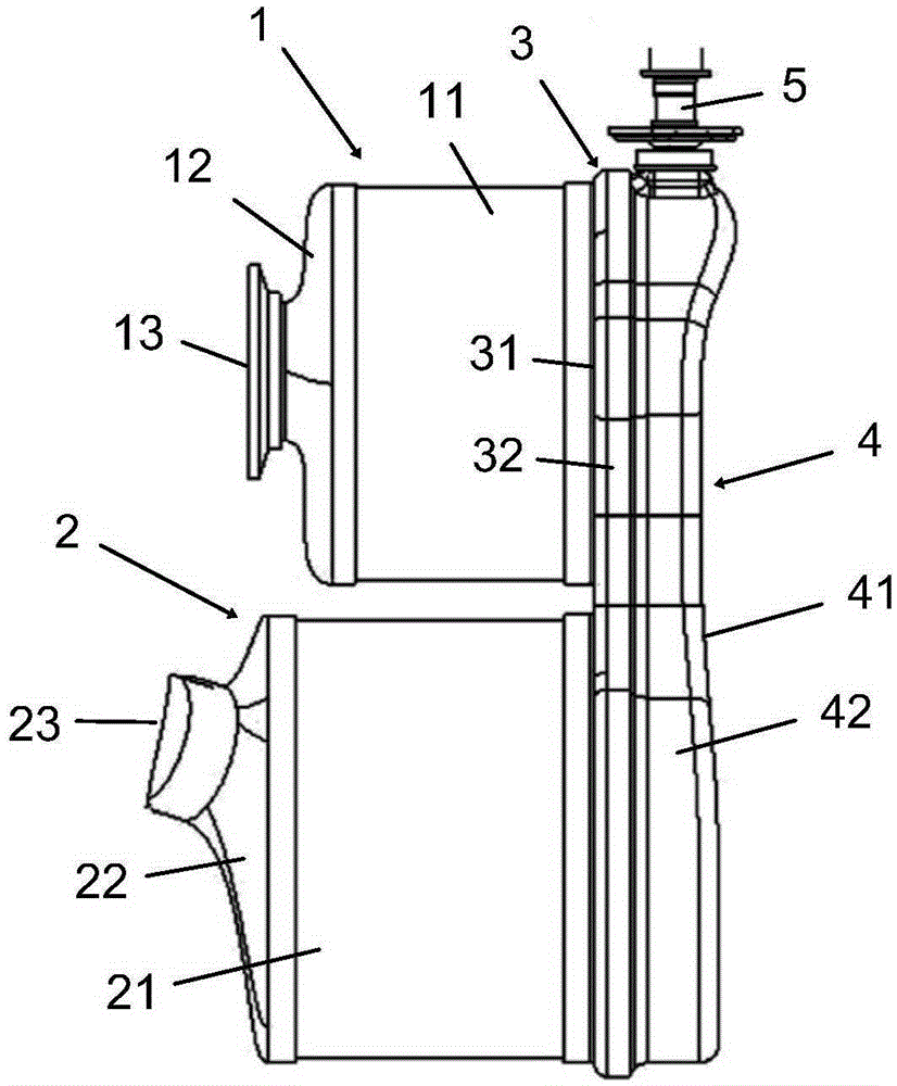
[0037] The present application generally relates to an exhaust aftertreatment system for treating engine exhaust, the exhaust aftertreatment system being installed in the engine compartment. The exhaust aftertreatment system of the present application is typically suitable for treating the exhaust of diesel engines; however, the exhaust aftertreatment system is also applicable to other types of engines (some components in the system may need to be modified accordingly).

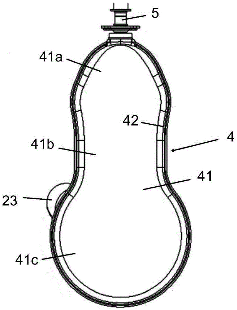
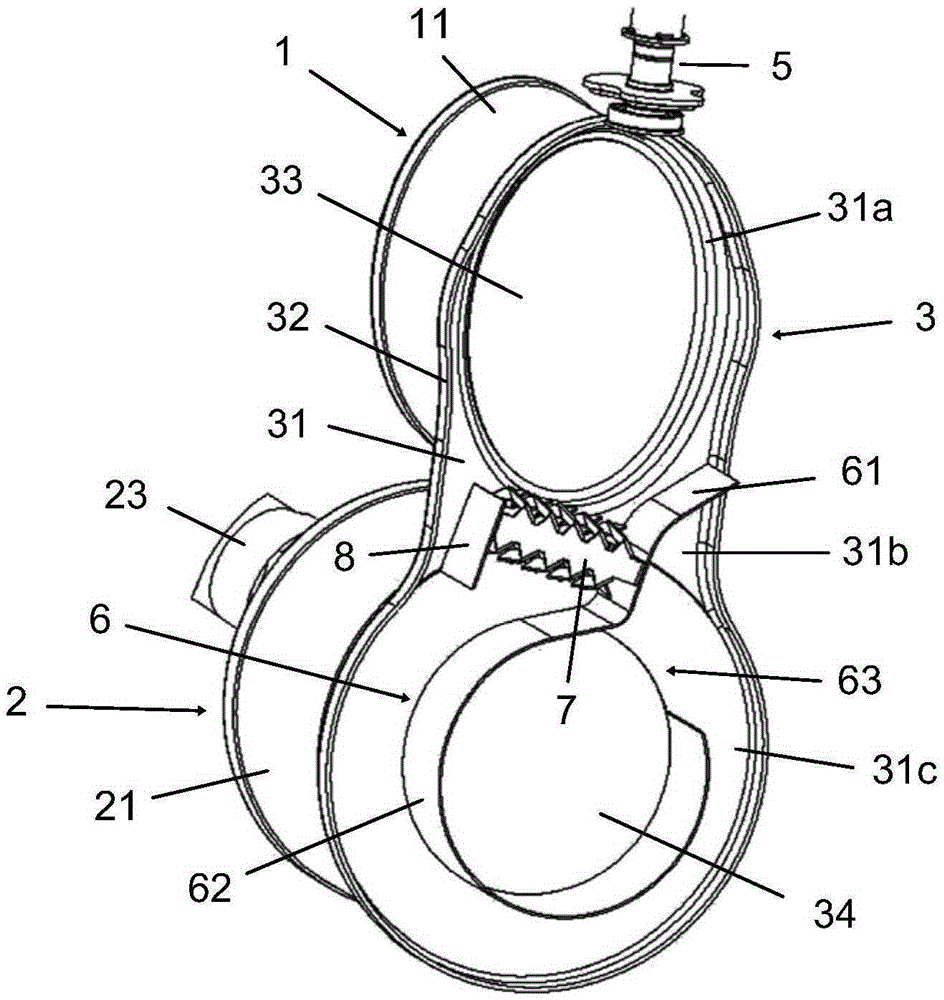
[0038] Figures 1 to 3 The integrated exhaust gas aftertreatment system of the present application is shown. The exhaust gas aftertreatment system mainly includes an oxidation catalyst unit 1 and a SCRoF unit 2 . The SCRoF unit 2 is a one-piece assembly in which the selective catalytic reduction function and the particle trapping (filtration) function are combined. The oxidation catalyst unit 1 and the SCRoF unit 2 are assembled in a first cover 3 , and the first cover 3 and the second cover 4 constitute a ...


PUM


Abstract

The invention discloses a tail gas aftertreatment system for treating engine tail gas. The system comprises a cover (3, 4) for limiting mixing chamber inside, an oxidation catalyst unit (1) and a SCRoF unit (2) assembled on the cover and both communicated with a fluid in the mixing chamber, a reducing agent metering module (5) mounted on the cover for spraying a reducing agent from the oxidation catalyst unit (1) into tail gas in the mixing chamber, and a cyclone guide piece (6) arranged in the mixing chamber and configured to guide a mixture of the tail gas and the reducing agent to flow into the SCRoF unit (2) from the mixing chamber in a cyclone manner.

Description

technical field [0001] The present application relates to an integrated aftertreatment system for treating exhaust gases emitted by an engine, in particular a diesel engine, which is configured for installation in an engine compartment. Background technique [0002] Engine exhaust contains harmful components. In order to reduce the emission of harmful components in exhaust gas, various after-treatment technologies have been developed. [0003] For example, a typical exhaust aftertreatment system for a diesel engine includes a diesel oxidation catalyst (DOC), a selective catalytic reduction module (SCR) and a diesel particulate filter (DPF). [0004] DOC, SCR and DPF can be arranged in series under the chassis of the vehicle. In this layout, since there is a relatively large available space, it is easy to arrange the various components. [0005] In another type of layout, the DOC, SCR and DPF are installed in the engine compartment. According to this arrangement, the afte...

Claims


Application Information

Patent Timeline
IPC IPC(8): F01N3/28
CPCF01N3/103F01N3/2066F01N3/2892F01N13/08F01N13/1872F01N13/1888F01N3/035F01N2470/22F01N2610/02F01N2610/1453Y02T10/12B01F23/2132B01F25/4315B01F25/431974
Inventor 唐宝宝罗晶
Owner ROBERT BOSCH GMBH
Why Eureka
Try Eureka