Cam shaft type combustion chamber variable-capacity piston internal combustion engine

A technology for internal combustion engines and combustion chambers, applied in engine components, engine control, machines/engines, etc., can solve the problems of high fuel consumption, high ignition power consumption, etc., and achieve the effects of reducing fuel consumption, improving fuel efficiency, and reducing internal friction

Active Publication Date: 2017-05-31
傅弃帆
View PDF12 Cites 2 Cited by
  • Summary
  • Abstract
  • Description
  • Claims
  • Application Information

AI Technical Summary

Problems solved by technology

[0003] The technical problem to be solved by the present invention is to provide a camshaft-type combustion chamber variable-capacity piston internal combustion engine to solve the problems of high pre-ignition power consumption and large fuel consumption in existing piston internal combustion engines

Method used


Image

  • Cam shaft type combustion chamber variable-capacity piston internal combustion engine
  • Cam shaft type combustion chamber variable-capacity piston internal combustion engine
  • Cam shaft type combustion chamber variable-capacity piston internal combustion engine

Examples


Embodiment 1

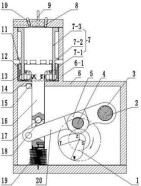
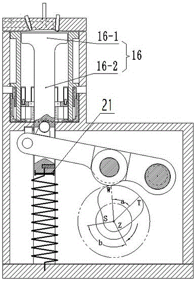
[0021] like figure 1 , figure 2 and image 3 The shown camshaft type combustion chamber variable displacement piston internal combustion engine includes a cylinder 7 and a piston 16 installed in the cylinder 7, a cylinder head is provided on the cylinder 7, and a fuel injector 10 and an intake valve 9 are provided on the cylinder head. And the spark plug 8; the cylinder 7 has a working section 7-3 and a fence exhaust section 7-1 with a plurality of notches distributed at the outer edge, and the openings of the plurality of notches face downwards. There is a limiting convex ring 7-2 at the connection of the fence exhaust part 7-1; the fence exhaust part of the cylinder 7 is inserted into the fence hole 11-2 distributed in the fence type exhaust valve 11, as shown in Figure 4 and Figure 5 shown; the fence type exhaust valve 11 slides on a plurality of annular vertical slideways of the exhaust valve sleeve 12 through the slider 11-1 on its outer edge, and the fence type exh...

Embodiment 2

[0023] The central angle a of the equal diameter flange area TW at the top dead center of the power cam 1 is 55°, and the central angle b of the equal diameter flange area SZ at the bottom dead center of the power cam 1 is 110°.

Embodiment 3

[0025] The central angle a of the equal diameter flange area TW at the top dead center of the power cam 1 is 50°, and the central angle b of the equal diameter flange area SZ at the bottom dead center of the power cam 1 is 108°.

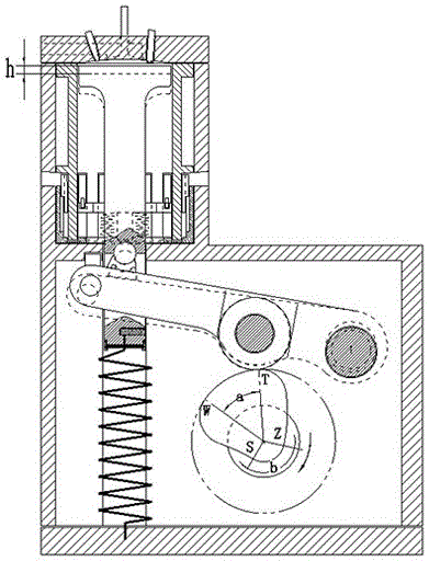
[0026] During operation, the mixed gas in the combustion chamber is ignited and an expansion force is generated to push the piston body 16-1, and the rod portion 16-2 of the piston 16 drives the rocker arm 3, and the rocker arm 3 rotates by pressing the power cam 1 downward, and the piston body works externally. When 16-1 runs to the vicinity of the bottom dead center, the piston body 16-1 continues to move downward under the combined action of inertia and return spring 19, and the piston body 16-1 drives the fence type exhaust valve 11 to move downward at the same time, and the cylinder The gas in 7 is discharged to the outside; the piston body 16-1 runs to the bottom dead center (the S point of the power cam), because at this time, the thrust pulley...


PUM


Abstract

The invention discloses a cam shaft type combustion chamber variable-capacity piston internal combustion engine and relates to the technical field of engine manufacturing. The cam shaft type combustion chamber variable-capacity piston internal combustion engine comprises an air cylinder and a piston arranged in the air cylinder. The piston is provided with a piston body and a rod part arranged at the bottom of the piston body. The rod part is fixed through a reset spring. A rocker arm is installed on a sheave shaft in a penetrating mode. A thrust sheave is arranged on the rocker arm, is installed on the sheave shaft in a penetrating mode, and abuts against the periphery of a power cam through the periphery of the thrust sheave. One end of the rocker arm penetrates through the rod part, and the other end of the rocker arm is provided with a capacity eccentric shaft in a sleeving mode. The central angle of the power cam comprises an upstream variable-diameter flange area ZT, an upper dead center equal-diameter flange area TW, a downstream variable-diameter flange area WS and a lower dead center equal-diameter flange area SZ. Compared with the prior art, the piston body stops for a certain period of time after reaching an upper dead center, advanced ignition is conducted at the moment, due to the fact that the piston body does not need to go upwards, power consumption of advanced ignition is avoided, and the internal consumption and oil consumption are substantially reduced.

Description

technical field [0001] The invention relates to the technical field of engine manufacturing, in particular to a piston internal combustion engine with a variable volume combustion chamber. Background technique [0002] At present, a piston internal combustion engine mainly includes a cylinder and a piston arranged in the cylinder, and the piston is connected to the crankshaft through a connecting rod. The mixed gas goes through four strokes in the cylinder, which are the intake stroke, the compression stroke, the working stroke and the exhaust stroke in sequence; The bottom dead center is completed; when the piston approaches the top dead center, the mixed gas is ignited by the electric spark, and the gas expands violently. Under the strong pressure of the gas, the piston moves rapidly at the bottom dead center, and pushes the connecting rod to drive the crankshaft to rotate. This stroke is The only stroke that enables the engine to work to gain power. Since the mixture ga...

Claims


Application Information

Patent Timeline
Patent Type & Authority Applications(China)
IPC IPC(8): F02D15/04F02B75/04F02F1/00F01L1/18F01L1/04F02D13/02
CPCF01L1/04F01L1/18F02B75/04F02D13/0269F02D15/04F02F1/004F02D2700/03F02B2275/32Y02T10/12
Inventor 傅弃帆
Owner 傅弃帆
Why Eureka
Try Eureka