
An Inducer Wheel to Suppress Cavitation Oscillation

A technology of inducer and cavitation, which is applied to components of pumping devices for elastic fluids, non-variable pumps, pump components, etc., to achieve the effects of reducing pulsation and vibration, optimizing structure, and suppressing cavitation oscillations

Active Publication Date: 2020-01-21
XIAN AEROSPACE PROPULSION INST
View PDF5 Cites 0 Cited by
  • Summary
  • Abstract
  • Description
  • Claims
  • Application Information

AI Technical Summary

Problems solved by technology

[0007] In order to solve the problem of cavitation oscillation caused by the cavitation of the inducer, the present invention provides an inducer, which can suppress the cavitation oscillation only by improving the local structure of the existing inducer, without adding additional parts, and the structure is simple and easy to realize

Method used


Image

  • An Inducer Wheel to Suppress Cavitation Oscillation
  • An Inducer Wheel to Suppress Cavitation Oscillation
  • An Inducer Wheel to Suppress Cavitation Oscillation

Examples


Embodiment Construction

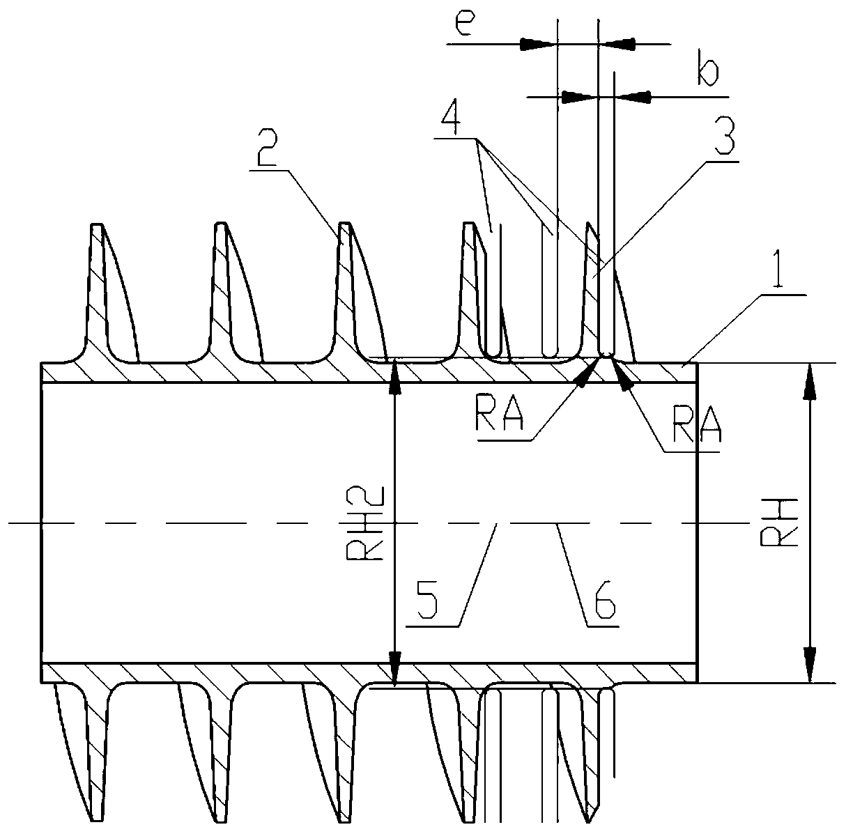
[0028] Such as figure 1 with Image 6 As shown, the inducer provided by the present invention includes a hub 1, a helical blade 2, an inlet guide part 3, and an annular groove 4 formed on the blade and penetrating from the blade tip to the hub. The axis 6 of the annular groove 4 coincides with the axis 5 of the inducer, the cross section of the annular groove is approximately rectangular, the diameter RH2 of the bottom of the annular groove is slightly larger than the diameter RH of the hub, and the bottom of the annular groove is rounded with RA.

[0029] Such as Figure 2a The expansion diagram of the existing equal-pitch inducer along the average diameter is given, and the placement angle β of the inducer blade in the figure is lcp , relative flow velocity ω 1cp , angle of attack i cp , cascade pitch t cp (t cp = πD cp / z in ,z in is the number of inducer blades). Such as Figure 2a The cavitation of the existing inducer shown in the figure occurs at the back of ...


PUM


Abstract

The invention provides an inducting wheel for inhibiting cavitation oscillation to solve the cavitation oscillation problem caused by cavitation of the inducting wheel. The inducting wheel comprises a wheel hub and spiral blades arranged outside the wheel hub. Ring-shaped grooves are formed in the blades in the inducting wheel cavitation in the direction from blade tips to the wheel hub. According to the inducting wheel for inhibiting cavitation oscillation, only a local structure of an existing inducting wheel is improved, and thus cavitation oscillation can be inhibited, extra parts do not need to be additionally-arranged, the structure is simple, and the inducting wheel is easy to achieve.

Description

technical field [0001] The invention belongs to the field of rotating machinery, and in particular relates to an inducer applied to a centrifugal pump. Background technique [0002] In liquid rocket engine turbopumps, in order to obtain smaller mass and greater thrust-to-mass ratio, the inducer in the high-speed inducer centrifugal pump often works under the condition of potential cavitation. Although the potential cavitation in the pump flow path will not have a significant impact on the steady-state output parameters (head, power, and efficiency) of the pump, it will change the dynamic characteristics of the system and cause pressure and flow in the hydraulic system under certain conditions. The self-excited oscillation and severe cavitation oscillation will reduce the reliability of the pump product and even lead to product damage. [0003] The traditional method to solve the cavitation oscillation of the pump supply system is to install a pressure accumulator on the sup...

Claims


Application Information

Patent Timeline
Patent Type & Authority Patents(China)
IPC IPC(8): F04D29/24F04D29/66F04D29/22
CPCF04D29/225F04D29/242F04D29/688
Inventor 李惠敏李向阳宣统陈晖王晓锋韩飞于晴李春乐毛凯张聃
Owner XIAN AEROSPACE PROPULSION INST
Learn More