

Buzzer automatic assembling equipment and assembling technology
An automatic assembly and buzzer technology, applied in mechanical equipment, welding equipment, resistance welding equipment, etc., can solve the problems of large space occupation, low efficiency of manual work, and difficulty in accurate control
- Summary
- Abstract
- Description
- Claims
- Application Information
AI Technical Summary
Problems solved by technology
Method used
Image

Examples
Embodiment 1
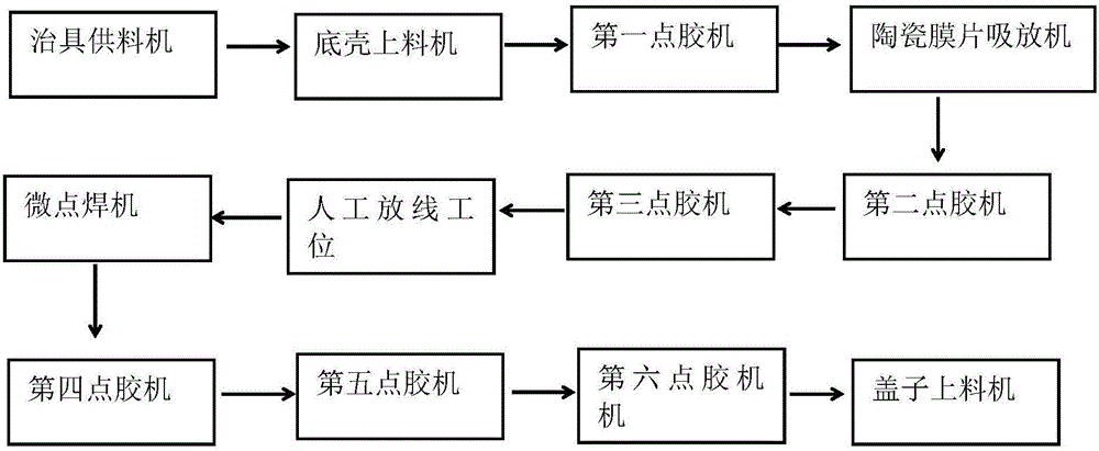
[0064] refer to figure 1 As shown, this embodiment discloses a buzzer automatic assembly equipment, the main structure of which includes a frame, the table of the frame is provided with an assembly line, the assembly line runs through each station on the assembly equipment, and the assembly equipment depends on The assembly process includes in turn: jig feeder, bottom shell loader, first dispensing machine, ceramic diaphragm suction and release machine, second dispensing machine, third dispensing machine, manual unloading station, micro-dot Welding machine, fourth glue dispenser, fifth glue dispenser, sixth glue dispenser, cover feeder.
[0065] The entire buzzer assembly process can be completed on the device, which improves the assembly efficiency and reduces the space occupied by the device.
[0066] The process in each of the above-mentioned stations is: the above-mentioned jig feeder automatically places the jig carrying the buzzer assembly on the above-mentioned assembl...
Embodiment 2
[0091] A buzzer assembly process is disclosed in Embodiment 2, comprising the following steps:
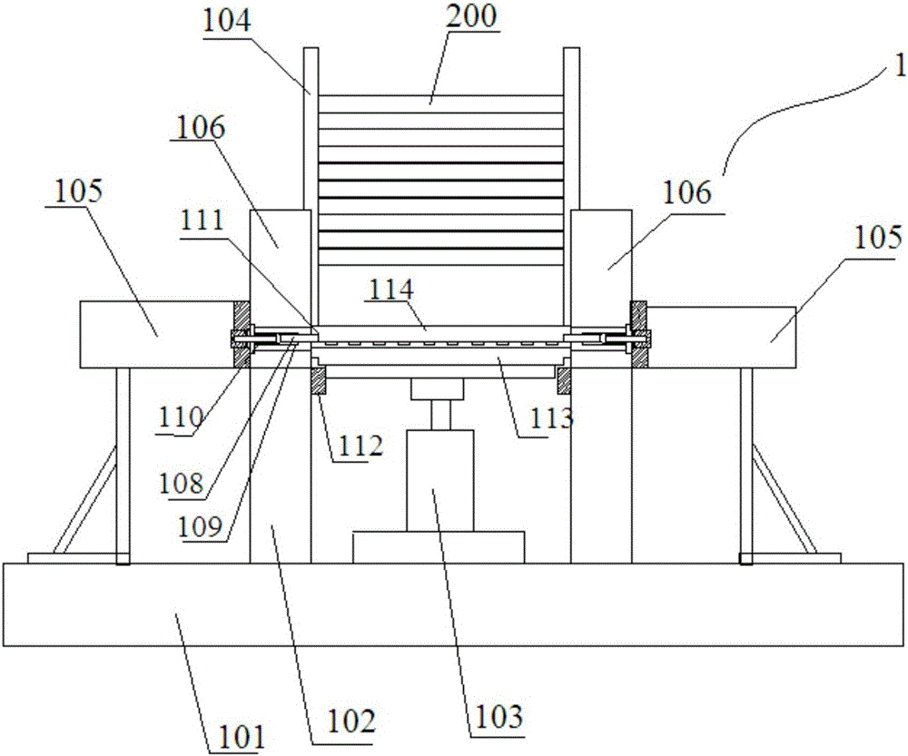
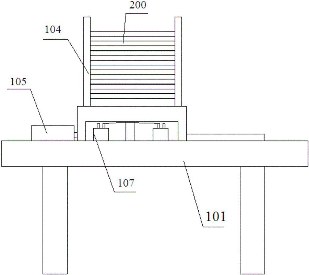
[0092] S101 Jig feeding: the jig loading assembly full of jigs is placed on the jig feeder, the cylinder rod of the pallet cylinder rises, and the above pallet cylinder holds up the bottom two jigs in the above jig loading assembly , which are the first jig and the second jig respectively, the intercepting pin is retracted in the through hole of the baffle plate, and then the cylinder rod of the supporting plate cylinder is lowered, the first jig and the second jig are descending, and the intercepting cylinder Drive the intercepting pin to push out the through hole, the above-mentioned intercepting pin extends into the intercepting hole of the second jig, intercepts the second jig, and after the pallet cylinder returns completely, the first jig is separated from the second jig, and the second jig A jig is mounted on the jig support slide, the push plate cylinder pushes the first ji...
PUM
 Abstract
Description
Claims
Application Information