Opposite-direction pressure relief equipment

A device and pressure release technology, applied in mechanical equipment, springs, shock absorbers, etc., can solve the problems of short stroke, insufficient energy absorption performance and limited energy, and achieve the effect of improving energy absorption capacity and increasing stroke

Inactive Publication Date: 2017-05-31
巴南区伟鹏机械加工厂
View PDF0 Cites 0 Cited by
  • Summary
  • Abstract
  • Description
  • Claims
  • Application Information

AI Technical Summary

Problems solved by technology

The disadvantage is that the energy that can be absorbed is limited and t

Method used


Image

  • Opposite-direction pressure relief equipment

Examples


Embodiment 1

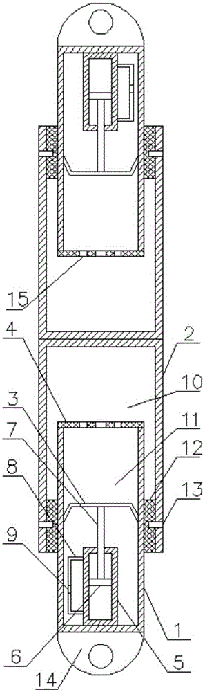
[0028] Such as figure 1 As shown, the opposing pressure relief equipment includes two interconnected pressure relief devices, the pressure relief device includes an inner cylinder 1, an outer cylinder 2, a floating piston 3, a damping body 4, a pressure storage cylinder 5, a piston 6, and a piston Rod 7, connecting pipe 8 and damping block 9; the upper end of the outer cylinder 2 is closed, the lower end of the outer cylinder 2 is open, the upper end of the inner cylinder 1 is open, and the lower end of the inner cylinder 1 is closed; the damping body 4 is arranged on the upper end of the inner cylinder 1 , the damping body 4 is provided with a damping hole; the floating piston 3 is set in the inner cylinder 1, the piston 6 is set in the pressure storage cylinder 5, the piston rod 7 runs through the top of the pressure storage cylinder 5 and is connected to the piston 6, and the pressure storage cylinder 5 Set in the inner cylinder 1 and connected to the bottom of the inner cy...

Embodiment 2

[0035] Such as figure 1 As shown, this embodiment is based on Embodiment 1, and a sealing support member 12 is provided between the bottom inner surface of the outer cylinder 2 and the outer surface of the inner cylinder 1 .

[0036] A sealing support member 12 is provided to avoid oil leakage in the outer cylinder.

Embodiment 3

[0038] Such as figure 1 As shown, this embodiment is based on Embodiment 2, and the sealing support member 12 is connected to the outer cylinder 2 through a pin shaft 13 .


PUM


Abstract

The invention discloses opposite-direction pressure relief equipment which comprises two pressure relief devices. The upper end of an outer barrel body is closed, and the lower end of the outer barrel body is open. The upper end of an inner barrel body is open, and the lower end of the inner barrel body is closed. A damping body is arranged at the upper end of the inner barrel body and provided with a damping hole and a thin and weak ring groove. A floating piston is arranged in the inner barrel body. A piston is arranged in a pressure storage cylinder. A piston rod penetrates through the top end of the pressure storage cylinder to be connected with the piston. The pressure storage cylinder is arranged in the inner barrel body and connected with the bottom end of the inner barrel body. The piston rod is connected with the floating piston. The two ends of a communicating pipe communicate with a rod cavity and a rodless cavity of the pressure storage cylinder correspondingly. A damping block is fixed in the communicating pipe and provided with small damping holes. The inner barrel body is arranged in the outer barrel body in a sliding mode. The opposite-direction pressure relief equipment is composed of the two pressure relief devices, so that the stroke is greatly increased, and the problems that an existing pressure relief device is short in stroke and cannot provide enough vibration attenuation performance are solved.

Description

technical field [0001] The invention relates to a pressure relief device. Background technique [0002] The pressure relief device is mainly used to absorb the impact from the road surface. When passing through uneven roads, filter the vibration of the road surface. Pressure relief devices are widely used in automobile suspension systems, rail vehicle suspension systems and aircraft landing gear systems. The main function of the pressure relief device is to filter the vibration of the road surface, but its more important role is to improve the comfort of passengers, reduce the impact on the chassis of the car, the frame of the rail vehicle and the fuselage of the aircraft, and the impact on the automobile, rail vehicle and aircraft. security plays an extremely critical role. [0003] The existing pressure relief device adopts an oil-air hybrid structure, which absorbs energy by using the damping generated when the oil passes through the damping hole, and then uses the com...

Claims


Application Information

Patent Timeline
IPC IPC(8): F16F9/22F16F9/36F16F9/32
CPCF16F9/22F16F9/3207F16F9/362
Inventor 余一祥
Owner 巴南区伟鹏机械加工厂
Why Eureka
Try Eureka