[0018]The measuring device may be provided with an optical device to display the reflected light on the measuring device, in particular on the 2D classification. Moreover, the
advantage of the invention applies in principle also to, for example,
triangulation measurements by means of one or more
laser beams, such as known for
red light for example from EP 1253440 which is hereby incorporated by reference in its entirety.
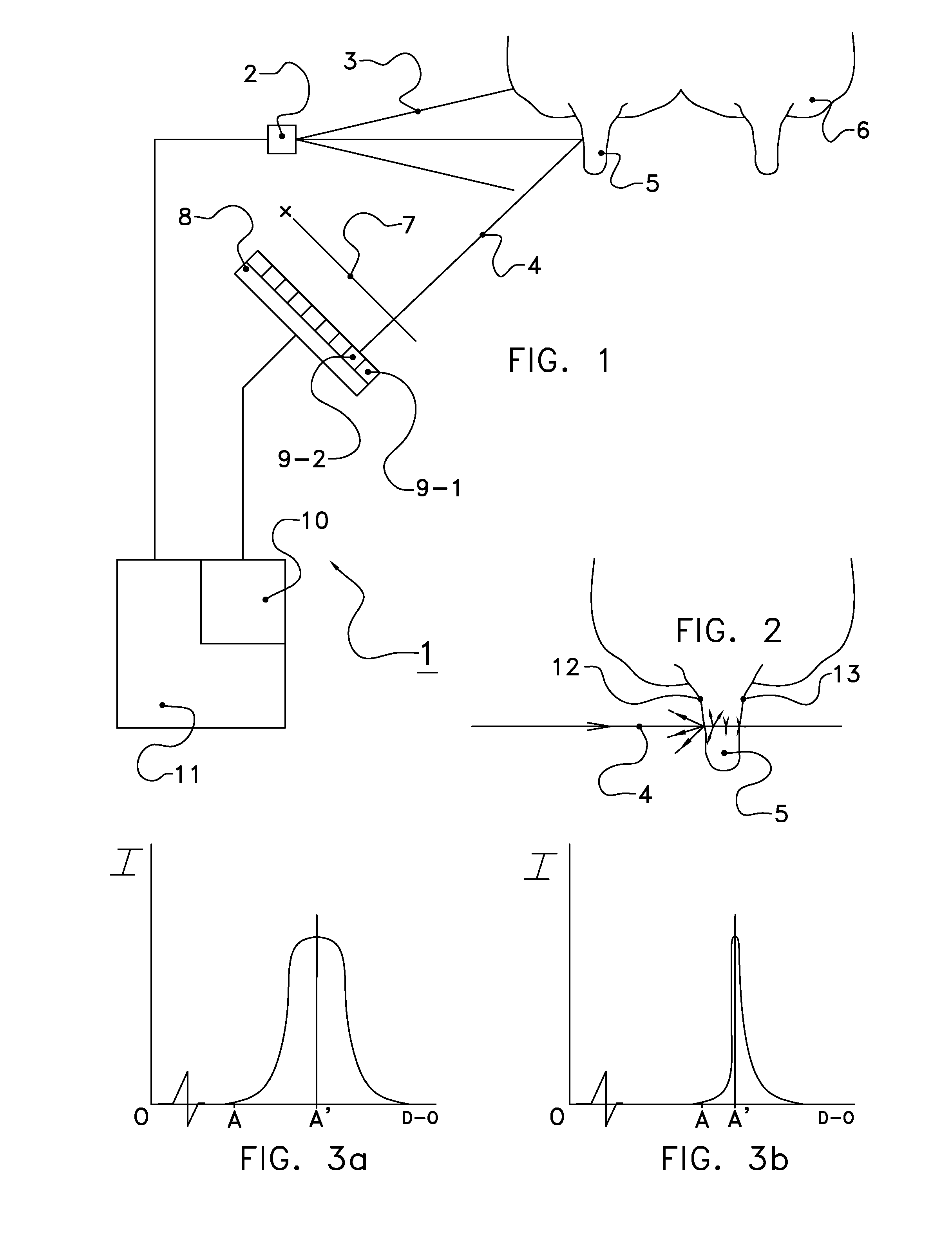
[0019]In particular, the device comprises an additional light source having an emission maximum with a wavelength between 600 and 1000 nm. The light source and / or the additional light source advantageously comprise(s) a LED or
laser. The light source and / or the additional light source advantageously comprise(s) a plurality of partial light sources, for a
higher power but also for a higher reliability in operation. For, it is possible for the device still to operate as a whole, also at a lower capacity as a result of poorly or not functioning of one or more partial light sources. The additional light source is preferably controllable by the control device which can advantageously alternate the light source and the additional light source, or operate them simultaneously, if desired. It should be noted here that it thus becomes possible to select a stronger or lower interference signal, which signal, of course, is partly determined by colour-dependent reflection properties. The additional light source may, in particular, advantageously be used for a first, rough
distance measurement. For, (near infra)red LED's or lasers with a great capacity are widely available, while this applies to a much lesser extent to, in particular, LED's in the
wavelength range according to the invention. The latter may then be used advantageously for the more precise position determination, for example after the rough position has first been determined. This is in particular the case if the capacity and / or the efficiency of the used shorter-wave-length light source are / is smaller than that / those of the additional light source. In practice, for example, a blue LED is often (much) less powerful than a (near infra)red LED, and has a lower efficiency. If the less strong or less efficient light source would also be used for the greater distances, such as the rough initial measurement / adjustment, this would be unnecessarily disadvantageous, causing more
energy consumption and / or cooling, or even a lower resolution, more interference and the like. By properly making use of the positive properties of both types of light, it is possible to achieve a particularly efficient detection device.
[0020]The light source(s) and / or the additional light source(s) are / is preferably positioned close to the light measuring device, so that the distance information becomes reliable by preventing different light paths.
[0021]In embodiments, the additional light source has a lower modulation frequency than that of the light source, in particular between 10 and 75 MHz. This provides an area of uniquely determinable distances between 2 and 15 metres, which is found to be a useful range. Other modulation frequencies are, however, not excluded. It should be noted that, for a time-of-flight sensor, it is not necessary to modulate the light source or the additional light source.
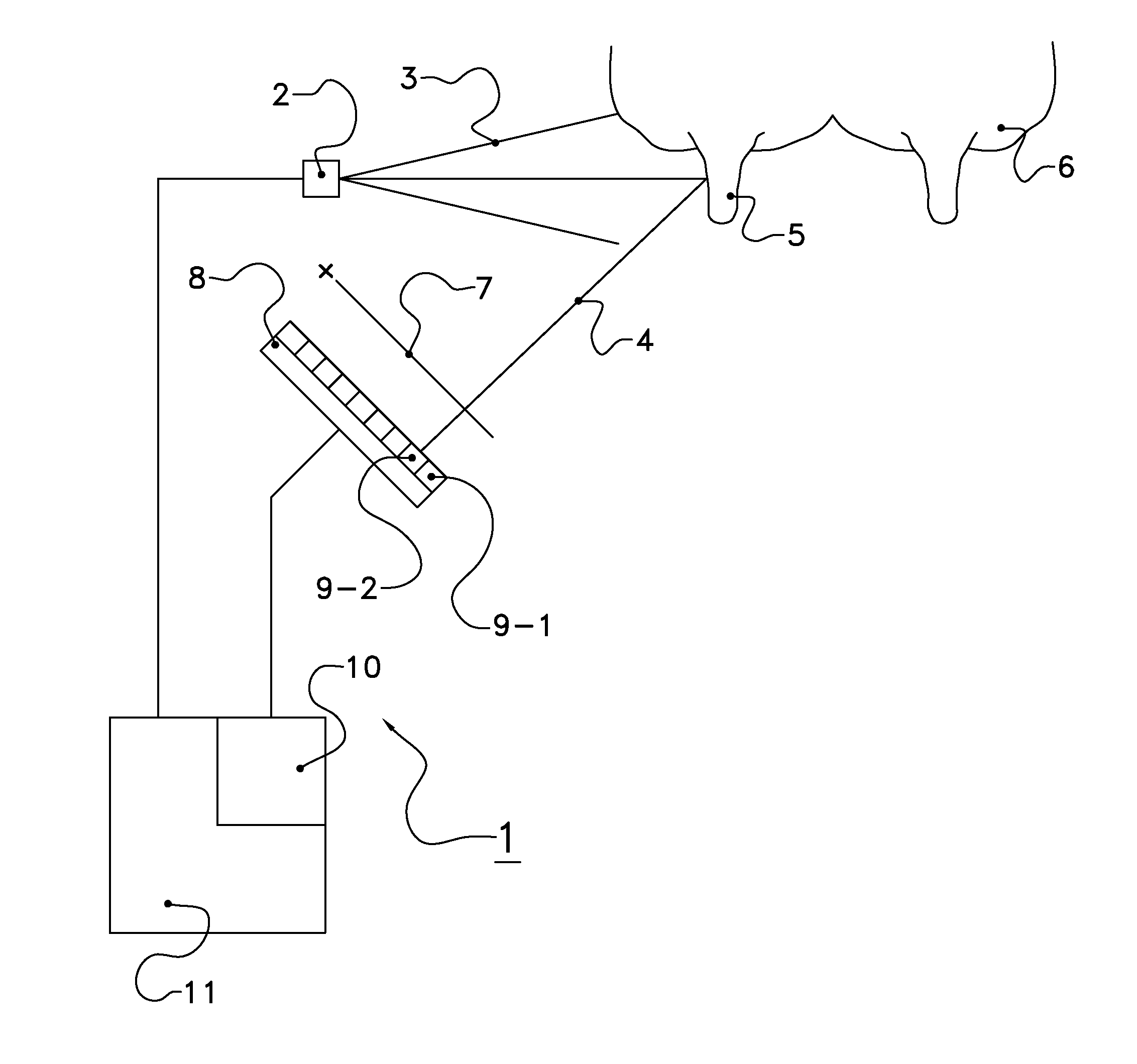
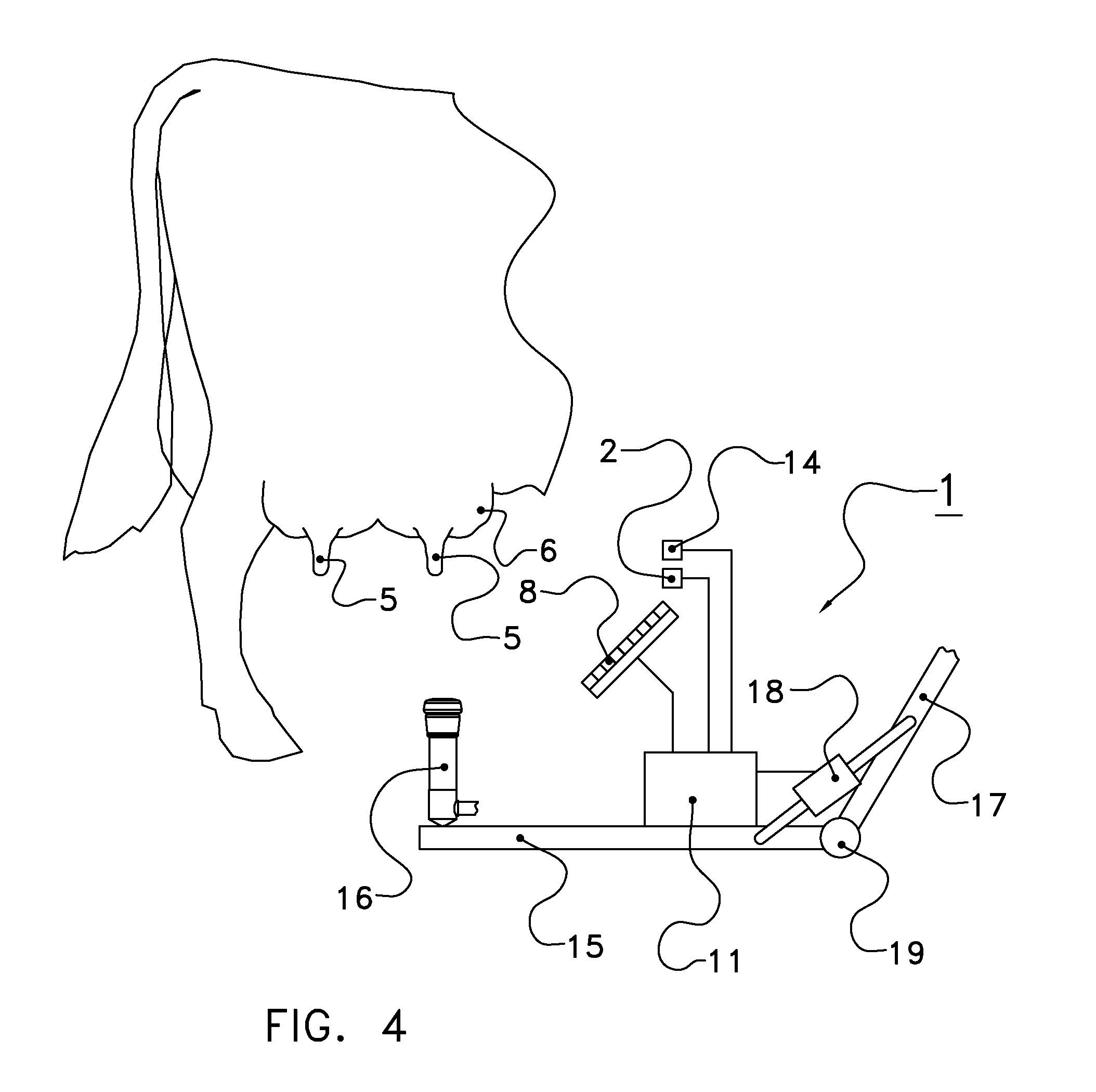
[0022]The invention also relates to an animal treating device for treating an animal, which comprises a detection device according to the invention. Examples are a
control room or the like, where an animal treatment is prepared, a feeding area or a feeding device, etc. In such cases, the detection device serves in particular to already determine a position of or distance to an
udder, teat etc., which can subsequently be used in or transmitted to, for example, a
milking box or the like, which is subsequently visited. An animal treating device is in particular a device which is arranged to position automatically, i.e. without human intervention being required, a part thereof or an external device or object with respect to an animal to be treated, in such a manner that an animal treatment can be performed by means of that component, device or object. In particular, the animal treating device relates to a device for automatically positioning a teat cup on a teat of a dairy animal, and more in particular to a robotic
milking device comprising a
robot arm for automatically applying a teat cup to an animal. However, the invention may, for example, also relate to a teat or
udder cleaning device or a teat or udder stimulating device. Such devices are already widely known per se, and are of major economic importance. Consequently, improving the positioning reliability by means of a detection device according to the invention is deemed to be of great importance. It should be noted that animals, and in particular
hairless parts thereof, such as teats, seem to have a relatively great transmissiveness of (infra)
red light, so that, here, the
advantage of the invention reveals itself clearly.
[0023]In particular, the animal treating device, more in particular a
robot arm control of a
robot arm thereof, is operatively connected to the detection device, for positioning the animal treating device with respect to the animal. Prior to the treatment, at least a part of the animal treating device or an external device or object will always be positioned with respect to the animal to be treated. If, for positioning, for example controlling a robot arm, use is made of position information obtained by means of the detection device, an enhanced reliability will be possible.

