Liquid outflow end opening switch device with one-way circulation mixer
A one-way flow, switch device technology, applied in valve devices, multi-way valves, engine components, etc., can solve the problems of blocking sensors or sensor failure, reliability not as good as mechanical operation transmission, signal transmission failure, etc. Simple, reduce waste of liquid resources, and reduce replacement costs
- Summary
- Abstract
- Description
- Claims
- Application Information
AI Technical Summary
Problems solved by technology
Method used
Image
Examples
Embodiment example 1
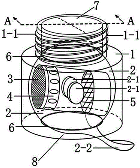
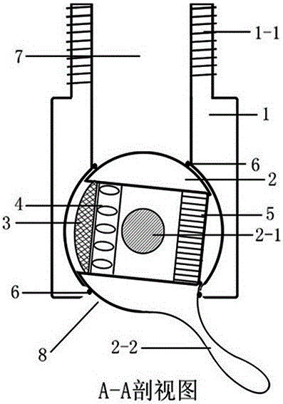
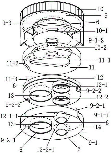
[0024] Implementation case 1 such as figure 1 , figure 2 , image 3 , Figure 4 , Figure 5As shown, the specific implementation method is: the device is a separate layout structure with the function of the one-way flow mixer and the function of the liquid outflow port switch, and the two are connected by a pipeline, and the pipeline is the liquid outflow that can satisfy the one-way flow mixer. The channel 13 is a pipe sealingly connected with the inflow port 7 of the liquid outflow port switch. The specific linking method is that there is a threaded port 1-1 at the inflow port 7 of the switch housing 1, which can be threaded with a pipeline container that is connected to the liquid outflow channel 13 of the one-way flow mixer and has a threaded interface. The pipe link is installed to the faucet as an example: overall, the installation method of the one-way flow mixer of this device is the same as that of the traditional cold and hot water mixer valve core installed in ...
Embodiment example 2
[0025] Implementation Case 2 Working Mode 1, the one-way flow mixer and the liquid outflow port switch are installed and used in combination, such as Figure 4 , Figure 5 As shown, for the convenience of illustration, liquid one Y1 or liquid two Y2 are all replaced by water, when water flows into the one-way flow mixer from the liquid one channel funnel-shaped inflow port 12-1-1 or the liquid two channel funnel-shaped inflow port 12-2 When -1, under the action of water pressure, the piston 14 is pushed away from the small-diameter end of the funnel-shaped inlet, and the large-diameter end of the funnel-shaped inlet is blocked by the first liquid channel grille 12-1 or the second liquid channel grille 12- 2. Under the interception, it is in the fixed position of the channel. At this time, the piston is in the open state 14-a. If the flow direction of water is opposite to that of the above-mentioned piston open state 14-a, it is in the piston closed state 14-b. When the piston...
Embodiment example 3
[0026] Implementation case 3 Working mode 2, only install the liquid outflow port switch in the device, remove the foamer at the port with the foamer on the original faucet body, and remove the foamer to let the liquid flow out of the port switch into the screw port 1 at the inlet 7 -1 screwed and installed to the original foamer position, the installation is complete. After the switch valve on the original faucet body is set to the open state, the liquid outflow port switch function in the device can be used. Toggle the switch valve body lever 2-2, the channel opening of the flow rate increasing unit 4 in the switch valve body 2 channel is intersected or aligned with the inflow port 7, and the channel port where the rectifier grid 5 is located is synchronously intersected or aligned with the outflow port 8 Positively, a channel through which liquid can flow is formed. At this time, the switch device of the liquid outflow port is in the open state. On the contrary, when the ab...
PUM
 Abstract
Description
Claims
Application Information
 - R&D
- Intellectual Property
- Life Sciences
- Materials
- Tech Scout
- Unparalleled Data Quality
- Higher Quality Content
- 60% Fewer Hallucinations
Browse by: Latest US Patents, China's latest patents, Technical Efficacy Thesaurus, Application Domain, Technology Topic, Popular Technical Reports.
© 2025 PatSnap. All rights reserved.Legal|Privacy policy|Modern Slavery Act Transparency Statement|Sitemap|About US| Contact US: help@patsnap.com


