Deep-recovery device for boiler flue gas waste heat

A boiler flue gas and recovery device technology, applied in the energy field, can solve the problems of unable to increase air temperature and humidity, reduce combustion temperature, and reduce exhaust gas temperature, so as to solve the problem of hard to find cold source, reduce combustion temperature, and increase dew point temperature Effect

Active Publication Date: 2017-05-31
TSINGHUA UNIV
View PDF8 Cites 5 Cited by
  • Summary
  • Abstract
  • Description
  • Claims
  • Application Information

AI Technical Summary

Problems solved by technology

In order to improve the above-mentioned heating device, the prior art discloses a centralized heating system that utilizes an absorption heat pump to recover waste heat from flue gas, and uses a flue gas-water direct contact heat exchanger to replace the dividing wall condensing heat exchanger to solve the problem of The corrosion problem of the metal heat exchange surface is solved; the existing technology discloses a heating system that uses a compression heat pump to realize the deep recovery of boiler waste heat, and gradually reduces the exhaust gas temperature of the boiler through three-stage heat exchange. To cool down the high-temperature flue gas and avoid the flue gas dew point area, the second-stage partition wall heat exchanger adopts resin material or heat pipe, and the third-stage heat exchanger adopts a combination of direct type and partition type, so as to realize the deep recovery of flue gas and solve the problem. Corrosion of metal heat exchange surfaces, however, both of these methods are based on heat pump equipment, the device structure is complex, the equipment is bulky and the cost is high
The prior art discloses a condensing boiler flue gas waste heat recovery device. A flue gas packing heat exchange tower and an air packing heat exchange tower are installed at the flue gas outlet of the condensing boiler. The boiler flue gas enters the flue gas packing heat exchange tower to cool down and dehumidify and discharge. The air is heated and humidified by the air-filled heat exchange tower and then enters the burner for combustion support. The hot water in the flue gas-filled heat exchange tower enters the air-filled heat exchange tower to exchange heat with the air, and then returns to the flue gas dryer to exchange heat with the flue gas. The air humidification can Improve the dew point of boiler flue gas, and at the same time reduce the combustion temperature and reduce NO x However, due to the nonlinear physical properties of the water vapor temperature and the corresponding saturated vapor pressure, the air temperature and humidity cannot be significantly increased, and the exhaust gas temperature is limited.

Method used


Image

  • Deep-recovery device for boiler flue gas waste heat
  • Deep-recovery device for boiler flue gas waste heat
  • Deep-recovery device for boiler flue gas waste heat

Examples


Embodiment 1

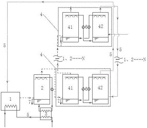
[0026] Such as figure 1 As shown, the boiler flue gas waste heat deep recovery device of the present invention includes a boiler 1, a steam-water heat exchanger 2, a water-water heat exchanger 3, N-level flue gas-air total heat heat exchange unit 4, and several pipelines 5 , a number of water pumps 6 and a number of overflow pipes 7, each level of flue gas-air total heat heat exchange unit 4 includes a flue gas-water heat exchanger 41 and an air-water heat exchanger 42, wherein, N≥2.

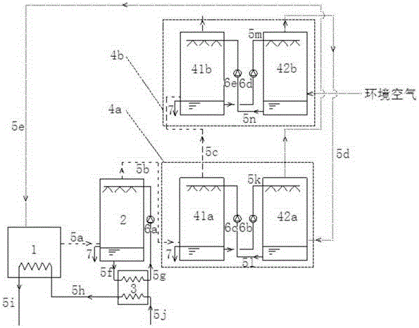
[0027]The present invention takes the two-stage flue gas-air total heat heat exchange unit 4 as an example to describe in detail the boiler flue gas waste heat depth recovery device of the present invention:

[0028] Such as figure 2 As shown, the flue gas-air total heat heat exchange unit 4 of this embodiment includes a high-temperature section flue gas-air total heat heat exchange unit 4a and a low-temperature section flue gas-air total heat heat exchange unit 4b, wherein the high-temperatur...

Embodiment 2

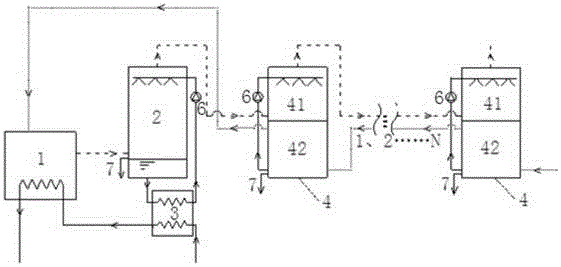
[0037] Such as Figure 7 As shown, the structure of this embodiment is basically the same as that of Embodiment 1, the difference is that this embodiment replaces the N-stage flue gas-air total heat heat exchange unit 4 of Embodiment 1 with a flue gas-water heat exchanger 41 from N-1 liquid distributors 8 are arranged at intervals from bottom to top. Correspondingly, N-1 water receiving trays 9 are arranged at intervals from top to bottom in an air-water heat exchanger 42, and each water receiving tray 9 is The water ports are connected to the water inlets of each liquid distributor 8, the bottom water outlet of the flue gas-water heat exchanger 41 is connected to the top water inlet of the air-water heat exchanger 42, and the bottom water outlet of the air-water heat exchanger 42 is connected to The top water inlet of the flue gas-water heat exchanger 41.

[0038] The present invention takes a liquid distributor 8 and a water receiving tray 9 as examples to describe in detai...


PUM


Abstract

The invention relates to a deep-recovery device for boiler flue gas waste heat. The deep-recovery device is characterized by comprising a boiler, a steam-water heat exchanger, a water-water heat exchanger and an N grades of flue-air total-heat exchange units, and each flue-air total-heat exchange unit comprises a flue-water heat exchanger and an air-water heat exchanger, wherein N is greater than or equal to 2. Compared with an existing recovery device for flue gas waste heat, the deep-recovery device has the advantages that the N grades of flue-air total-heat exchange units or a flue-water heat exchanger with N-1 liquid distribution units and an air-water heat exchanger with N-1 water pans are arranged, total-heat exchange of flue and air which are equivalent in temperature grade is performed respectively, temperature in flue outlet can be lowered by regulating spray water at all grades, temperature in the air outlet is raised, a flux matching state is achieved, problems about nonlinearity of a water steam saturation line and the like are solved, total-heat exchange efficiency of the flue and the air is remarkably improved, and the deep-recovery device is widely applicable to recovery devices of the boiler flue gas waste heat.

Description

technical field [0001] The invention relates to a boiler flue gas waste heat deep recovery device, in particular to a boiler flue gas waste heat deep recovery device used for boiler flue gas waste heat recovery and reduction of nitrogen oxide emissions, and belongs to the field of energy technology. Background technique [0002] Fuels such as natural gas, oil, and biomass contain a large amount of hydrogen, and boiler combustion produces a large amount of water vapor, such as 1m 3 The combustion of natural gas will produce 1.55kg of water vapor, and the latent heat is about 3600kJ, which accounts for 10% of the low calorific value of natural gas. Therefore, if the flue gas temperature can be lowered below the dew point and this part of latent heat can be recovered, it will play an important role in saving fuel consumption. On the other hand, the flue gas produced by boiler combustion contains a large amount of nitrogen oxides NO x , will cause air pollution, so effective me...

Claims


Application Information

Patent Timeline
Patent Type & Authority Applications(China)
IPC IPC(8): F23J15/06
CPCF23J15/06Y02E20/30
Inventor 王静贻付林赵玺灵张世钢华靖
Owner TSINGHUA UNIV
Why Eureka
Try Eureka