Movable dehumidifier with multipurpose integrated water drainage structure

A technology of drainage structure and dehumidifier, applied in application, household heating, household heating and other directions, can solve the problems of single market demand, unfavorable development, inconvenient operation, etc.

Active Publication Date: 2017-05-31
JIANGSU YOAU ELECTRIC CO LTD
View PDF10 Cites 8 Cited by
  • Summary
  • Abstract
  • Description
  • Claims
  • Application Information

AI Technical Summary

Problems solved by technology

Manual drainage is to manually remove the water tank for drainage. Water pump drainage is to use the water pump to directly discharge the water in the water receiving tray. There is also an auxiliary drainage port on the dehumidifier with the water pump. The auxiliary drainage port is directly connected to the drainage pan. Water level difference for drainage, that is, when the water level in the water tray reaches a certain height, it flows out naturally through the auxiliary drainage port, which can be used in combination with the water pump to save power consumption; but these two drainage methods have great defects: 1) Manual drainage needs to remove the water tank, and then reinstall the water tank after the drainage is completed. It is inconvenient to operate and the water tank is heavy. This drainage method is especially inconvenient for women and the elderly; 2) The lift of the water pump can reach more than 5 meters, and an external Drainage hoses are mainly used in basements, libraries or living rooms where drainage pipes are arranged. At present, the company's market for this type of products is mainly concentrated in Europe, North America and China. The external connection used in the European market, North America market and domestic market The diameters of the hoses are different, 10mm, 20mm and 6mm respectively. The outer diameter of the product drains produced by the company can only meet the needs of a single market, and cannot meet the needs of multiple markets at the same time, which is extremely unfavorable for the development of the company; Due to multiple market demands, there are multiple drains of different specifications at different positions on the shell of the dehumidifier; the increase of drains has great defects in many aspects: in terms of user use, the increase of drains greatly improves It is difficult for users to find the corresponding drains and installation; in terms of production technology, the increase of drains complicates the production process, adding multiple process steps, which greatly increases the difficulty and cost of production; in terms of space utilization, the drains are in the Different locations have a huge space span, and each outlet is equipped with a quick connector. There is no doubt that multiple pipelines will be added inside the dehumidifier to lead to each outlet, which occupies the limited internal space of the dehumidifier and wastes its space resources. , the internal pipeline laying and component installation are crowded in a small space, resulting in space blockage, increasing design difficulty, and in severe cases, it will affect the normal operation of each component; in terms of sealing, the increase of the drain greatly reduces the dehumidifier. The overall sealing effect increases the possibility of water leakage of the machine itself, affects customer use and market sales, greatly reduces the company's sales market area, and affects the company's performance; each drain is docked with the external quick connector, not only the docking structure is complicated, but also fast Joints are expensive and increase production costs

Method used


Image

  • Movable dehumidifier with multipurpose integrated water drainage structure
  • Movable dehumidifier with multipurpose integrated water drainage structure
  • Movable dehumidifier with multipurpose integrated water drainage structure

Examples


Embodiment 1

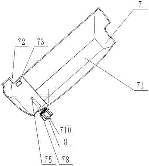
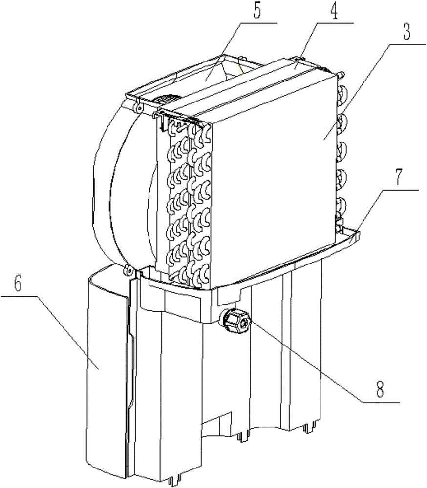
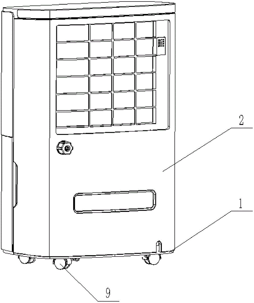
[0023] Embodiment 1: as Figure 1-5As shown, a mobile dehumidifier with a multi-purpose integrated drainage structure includes a base 1 and an outer shell 2 installed on the base 1. The outer shell 2 is equipped with an evaporator 3, a condenser 4, and an air supply system 5 And the water tank 6, the water tank 6 is located at the lower side of the outer shell 2, the air supply system 5 is installed above the water tank 6, and a condenser 4 and an evaporator 3 are successively arranged on one side of the air supply system 5; 4 and the integrated drainage structure 7 under the evaporator 3. The integrated drainage structure 7 is a concave structure composed of a water receiving tray 71 and a water tank 72. The humid air is formed after heat exchange between the condenser 4 and the evaporator 3 Condensed water falls in the water receiving tray 71 and then flows into the water tank 72. One end of the bottom surface of the water tank 72 is provided with a water tank water inlet 73...

Embodiment 2

[0029] Embodiment 2: as Figure 4 As shown, the outer surface of the second drain hole 78 is threaded. It also includes a reinforced fixed seal cover 8 with a concave structure installed on the end surface of the limit sealing boss 711, and its inner surface is provided with a thread matching the external thread of the second drainage hole 78, and the two are sealed and screwed together. The sealing cover 8 is used to further compress and fix the position-limiting sealing boss 711 on the outer end surface of the first drainage hole 77 . Such as figure 2 As shown, in order to facilitate the movement of the dehumidifier, several universal wheels 9 are provided under the base 1 .


PUM


Abstract

The invention relates to a movable dehumidifier with a multipurpose integrated water drainage structure. The movable dehumidifier comprises a base and an outer shell installed on the base. The outer shell is internally provided with an evaporator, a condenser, an air supply system and a water tank. The water tank is located on the lower side of the outer shell. The air supply system is installed above the water tank. The condenser and the evaporator are sequentially arranged on one side of the air supply system. The movable dehumidifier further comprises the integrated water drainage structure arranged below the condenser and the evaporator. Three water drainage modes are achieved, water drainage openings are integrated on the same structure without being additionally arranged at different positions on the outer shell, the production process is greatly simplified, processing is easy, the limited internal space of the dehumidifier is effectively saved, and the overall sealing effect is greatly improved.

Description

technical field [0001] The invention relates to the technical field of dehumidifiers, in particular to a mobile dehumidifier with a multi-purpose integrated drainage structure. Background technique [0002] With the improvement of living standards, people have higher and higher requirements for the quality of life, and there are certain requirements for the humidity of the air. In some special places, such as underground garages, due to the relatively high humidity all year round, in order to prevent items in the garage from Rust, the humidity in the garage must be controlled with a dehumidifier. Dehumidifiers are widely used and have penetrated into every aspect of people's lives. Dehumidifiers on the market include chassis, base, quick connectors, evaporators, condensers, water trays, drainage tanks, water collection tanks and other components. The evaporator is set on the side of the air suction port. The middle gasification absorbs heat, so the evaporator is in a low t...

Claims


Application Information

Patent Timeline
Patent Type & Authority Applications(China)
IPC IPC(8): F24F13/22
CPCF24F13/222
Inventor 陆军侯成才
Owner JIANGSU YOAU ELECTRIC CO LTD
Why Eureka
Try Eureka