Powder oscillation kiln

A kind of kiln and powder technology, applied in the direction of furnace, furnace type, lighting and heating equipment, etc., to achieve the effect of labor saving, reliable temperature control and high precision

Pending Publication Date: 2017-05-31
王延兵
View PDF3 Cites 2 Cited by
  • Summary
  • Abstract
  • Description
  • Claims
  • Application Information

AI Technical Summary

Problems solved by technology

[0003] The purpose of the present invention is to provide a powder oscillating kiln aiming at the technical defects of the prior art, so as to solve the technical problem that the powder calcination equipment in the prior art requires manual feeding and unloading operations

Method used


Image

  • Powder oscillation kiln

Examples


Embodiment 1

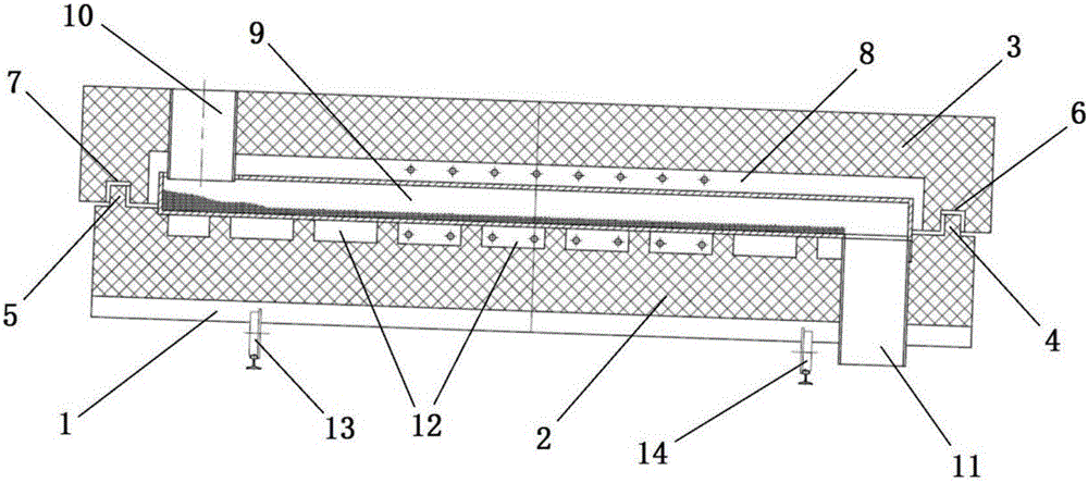
[0032] A powder oscillating kiln, including a base plate 1, a base 2, an upper cover 3, a first strip-shaped protrusion 4, a second strip-shaped protrusion 5, a first strip-shaped groove 6, and a second strip-shaped groove 7 , cavity 8, refractory pipe 9, feed pipe 10, discharge pipe 11, vibrating motor 12, first bracket 13, second bracket 14, wherein the base 2 is fixedly connected to the base plate 1, and the upper surface of the base 2 is on both sides There are first strip-shaped protrusions 4 and second strip-shaped protrusions 5 respectively, and both sides of the lower surface of the upper cover 3 have first strip-shaped grooves 6 and second strip-shaped grooves 7 respectively, and the first strip-shaped protrusions 4 matches the shape of the first strip-shaped groove 6, the second strip-shaped protrusion 5 matches the shape of the second strip-shaped groove 7, and the upper cover 3 passes through the first strip-shaped groove 6 and the second strip-shaped groove. The g...

Embodiment 2

[0039] A powder oscillating kiln, including a base plate 1, a base 2, an upper cover 3, a first strip-shaped protrusion 4, a second strip-shaped protrusion 5, a first strip-shaped groove 6, and a second strip-shaped groove 7 , cavity 8, refractory pipe 9, feed pipe 10, discharge pipe 11, vibrating motor 12, first bracket 13, second bracket 14, wherein the base 2 is fixedly connected to the base plate 1, and the upper surface of the base 2 is on both sides There are first strip-shaped protrusions 4 and second strip-shaped protrusions 5 respectively, and both sides of the lower surface of the upper cover 3 have first strip-shaped grooves 6 and second strip-shaped grooves 7 respectively, and the first strip-shaped protrusions 4 matches the shape of the first strip-shaped groove 6, the second strip-shaped protrusion 5 matches the shape of the second strip-shaped groove 7, and the upper cover 3 passes through the first strip-shaped groove 6 and the second strip-shaped groove. The g...


PUM


Abstract

The invention provides a powder oscillation kiln; the technical scheme designs a brand new internal structure by matching with the powder calcining process characteristics; an upper cover and a base, buckled with each other, are used for forming a closed cavity; the cavity serves as heating space; and meanwhile, a refractory pipe for accommodating powder is arranged in the heating space. On the basis, the refractory pipe is slightly inclined, and is provided with a vibration motor at the bottom, so that the sling movement of the powder in the refractory pipe can be realized through a vibration effect; and the mode not only can realize progressive movement of the powder in the pipe, but also can accelerate the heated speed and the heating uniformity through a microscopic throwing effect. In addition, a feed pipe and a discharge pipe are respectively arranged at two ends of the refractory pipe, so that the continuous operation of powder calcining can be realized through continuous charging and unloading. The powder oscillation kiln realizes excellent technical effects by innovative technical improvement, and meanwhile, is lower in cost, liable to realize and excellent in popularization prospect.

Description

technical field [0001] The invention relates to the technical field of powder calcination, in particular to a powder vibration kiln. Background technique [0002] At present, domestic high-temperature powder sintering mostly uses traditional push plate kilns, roller kilns and tunnel kilns in container methods such as bowls, so energy consumption is high, manual labor is used, automation is not easy to achieve, and dust is not environmentally friendly. Rotary kiln heating has a low calcination temperature, and gas-fired rotary kiln material recovery requires cooling equipment and recovery equipment, so the cost is high, and precise control of the material heating curve cannot be achieved. Especially ultrafine inorganic powder materials are widely used in chemical industry, electronics, metallurgy, medicine, food, ceramics and other industries. There are extremely high requirements on the purity and fineness of materials. Therefore, the finishing of such new materials, as a ...

Claims


Application Information

Patent Timeline
Patent Type & Authority Applications(China)
IPC IPC(8): F27B9/22F27B9/40
CPCF27B9/22F27B9/40
Inventor 王延兵
Owner 王延兵
Why Eureka
Try Eureka