Condensate water waste heat recycling and utilization device

A technology of waste heat recovery and condensed water, applied in heat exchange equipment, heat exchanger types, indirect heat exchangers, etc., can solve the problems of reducing the service life of cooling towers, heavy cooling tower workload, and increasing production costs of enterprises. Improve heating efficiency, save heating energy, and improve cooling efficiency

Inactive Publication Date: 2017-05-31
NINGBO CITY HANGZHOUWAN NEW DISTRICT XIANGYUAN POWER SUPPLYING
View PDF4 Cites 2 Cited by
  • Summary
  • Abstract
  • Description
  • Claims
  • Application Information

AI Technical Summary

Problems solved by technology

This method directly passes all the high-temperature condensed water into the cooling tower for cooling, which not only makes the working load of the cooling tower too large, reduces the service life of related components in the cooling tower, but also cools a large amount of high-temperature cooling water at the same time. , the cooling efficiency is low, and the cooling effect is poor. It often happens that the condensed water is discharged from the cooling tower before it has cooled to the required temperature, resulting in insufficient cooling capacity of the condensed water in the workshop.
In addition, high-temperature condensed water contains a large amount of heat energy. If the cooling tower is directly used to dissipate heat, it will cause huge waste of energy and increase the production cost of the enterprise.

Method used


Image

  • Condensate water waste heat recycling and utilization device

Examples


Embodiment 1

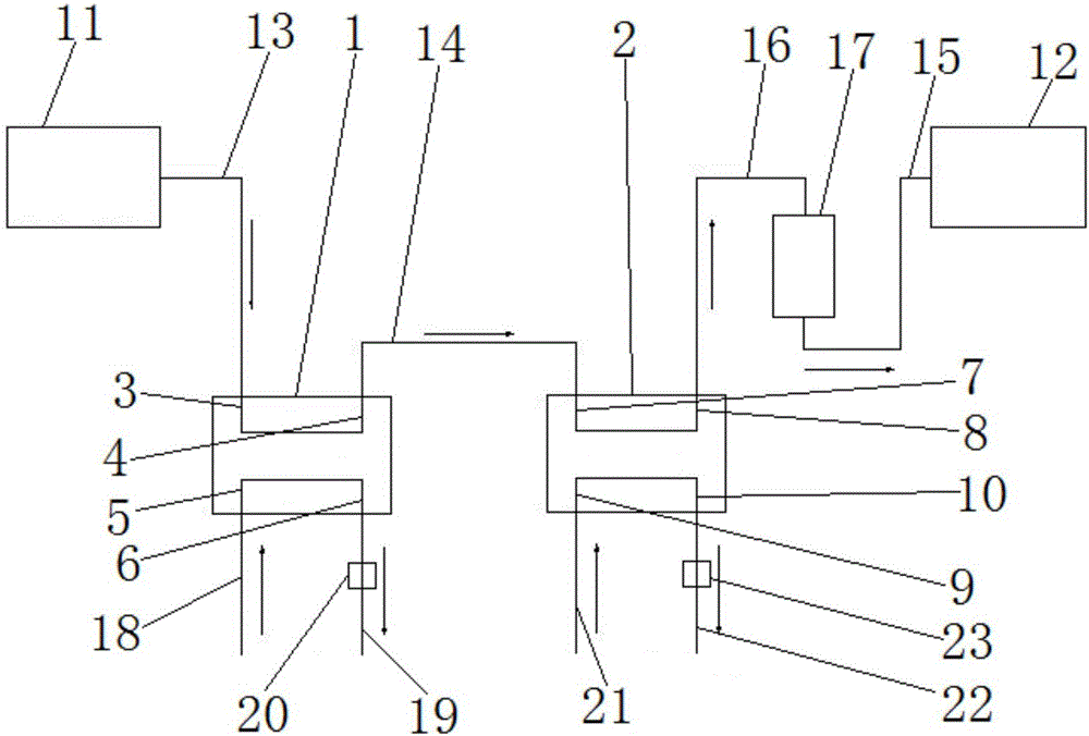
[0025] Such as figure 1 The condensed water waste heat recovery and utilization device includes a condensed water circulation unit, a process return water circulation unit, a domestic return water circulation unit, a first heat exchanger 1 and a second heat exchanger 2, the first heat exchanger 1 and the The second heat exchanger 2 is a plate heat exchanger. The first heat exchanger 1 is respectively provided with a water inlet pipe 3 on the high temperature side of the first heat exchanger, a water outlet pipe 4 on the high temperature side of the first heat exchanger, a water inlet pipe 5 on the low temperature side of the first heat exchanger, and a water inlet pipe 5 on the low temperature side of the first heat exchanger. The water outlet pipe 6 and the process return water circulation unit are respectively connected with the water inlet pipe 5 on the low temperature side of the first heat exchanger and the water outlet pipe 6 on the low temperature side of the first heat...

Embodiment 2

[0031] In this embodiment, the process circulating water heater 20 is a gas heater, the domestic circulating water heater 23 is a gas heater, and the rest are the same as in Embodiment 1.


PUM


Abstract

The invention relates to a condensate water waste heat recycling and utilization device which comprises a condensate water circulating unit, a technological returned-water circulating unit, a living returned-water circulating unit, a first heat exchanger and a second heat exchanger. The technological returned-water circulating unit communicates with a low-temperature-side water feeding pipe of the first heat exchanger and a low-temperature-side water discharging pipe of the first heat exchanger correspondingly, and the living returned-water circulating unit communicates with a low-temperature-side water feeding pipe of the second water exchanger and a low-temperature-side water discharging pipe of the second heat exchanger correspondingly; the condensate water circulating unit comprises a high-temperature condensate water box and a low-temperature condensate water box, and the high-temperature condensate water box communicates with the low-temperature condensate water box after passing through a high-temperature-side water feeding pipe of the first heat exchanger, a high-temperature-side water discharging pipe of the first heat exchanger, a high-temperature-side water feeding pipe of the second water exchanger and a high-temperature-side water discharging pipe of the second heat exchanger. Compared with the prior art, cooling of condensate water and heating of technological circulated-water returned-water and living circulated-water returned-water are integrated, the heat utilization rate is high, energy is saved, and consumption is lowered.

Description

technical field [0001] The invention belongs to the technical field of condensed water circulation, and relates to a condensed water waste heat recycling device. Background technique [0002] The high-temperature condensate discharged from the steam system has a temperature of about 90-100°C. Existing high-temperature condensed water is often discharged directly, or used as circulating cooling water after cooling to provide cooling capacity for workshop equipment. High-temperature condensed water is generally directly exchanged with fast-flowing air in the cooling tower to become low-temperature condensed water, and then passed into the workshop as a cold source. This method directly passes all the high-temperature condensed water into the cooling tower for cooling, which not only makes the working load of the cooling tower too large, reduces the service life of related components in the cooling tower, but also cools a large amount of high-temperature cooling water at the s...

Claims


Application Information

Patent Timeline
Patent Type & Authority Applications(China)
IPC IPC(8): F28D9/00F28F27/00
CPCF28D9/00F28F27/00
Inventor 郑铁君平诗磊张松吉
Owner NINGBO CITY HANGZHOUWAN NEW DISTRICT XIANGYUAN POWER SUPPLYING
Why Eureka
Try Eureka