Fiber optic F-P sound pressure sensor based on metal film

A sound pressure sensor, metal pattern technology, applied in the coupling of instruments, optical waveguides, measuring ultrasonic/sonic/infrasonic waves, etc. Improve detection accuracy, improve deformation, and reduce the effect of production cycle

Inactive Publication Date: 2017-05-31
HARBIN INST OF TECH
View PDF1 Cites 6 Cited by
  • Summary
  • Abstract
  • Description
  • Claims
  • Application Information

AI Technical Summary

Problems solved by technology

[0006] Aiming at the problem of the diaphragm material and diaphragm shape of the diaphragm-type optical fiber F-P sound pressure sensor, the invention discloses a fiber optic F-P sound pressure sensor based on a metal textured film; The diaphragm processing technology of silicon nitride material is complex, the production cycle is long, and the cost is high, and the thickness of the diaphragm based on PET material cannot be reduced due to the processing technology, which reduces the mechanical sensitivity; by changing the shape of the diaphragm, Solve the problem that the surface shape error is transmitted to the reflected light signal, causing errors in the reflected light signal and reducing the accuracy of detection

Method used


Image

  • Fiber optic F-P sound pressure sensor based on metal film
  • Fiber optic F-P sound pressure sensor based on metal film
  • Fiber optic F-P sound pressure sensor based on metal film

Examples


specific Embodiment 1

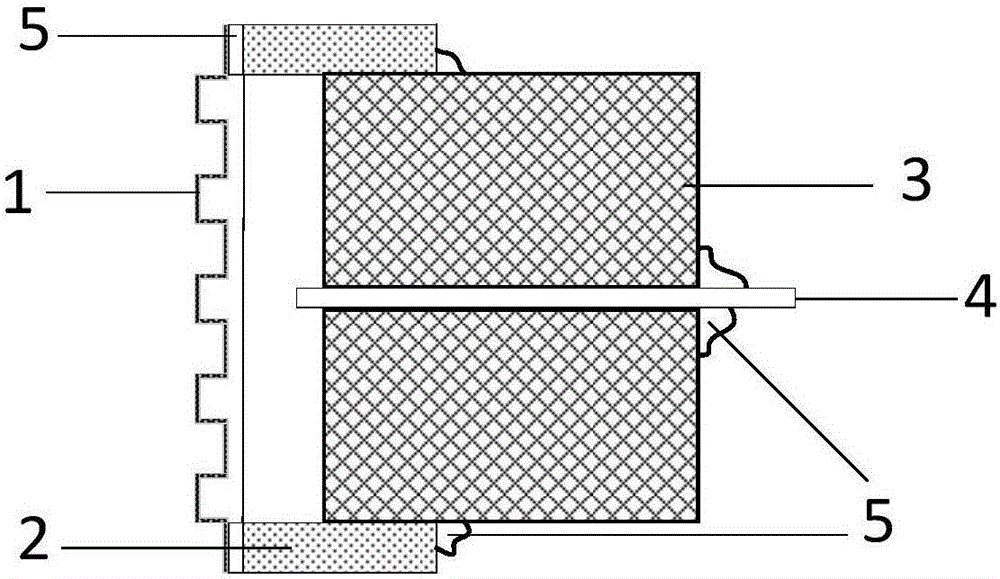
[0042] The optical fiber F-P sound pressure sensor based on the metal pattern film of the present embodiment, the structure schematic diagram is as follows figure 1 shown. The optical fiber F-P sound pressure sensor based on the metal pattern film includes a metal corrugated film 1, a through-cavity sleeve 2, a ferrule 3 and an optical fiber 4; One end face of the lumen sleeve 2 is inserted with a ferrule 3 matching the inner wall of the lumen sleeve 2 from the other end face of the lumen sleeve 2, and an optical fiber 4 with a polished end face is inserted in the center of the ferrule 3; the through lumen sleeve 2. The ferrule 3 and the optical fiber 4 are coaxially arranged, the sleeve 2 and the ferrule 3 are fixed with curing glue 5, and the ferrule 3 and the optical fiber 4 are fixed with curing glue 5; the metal corrugated film 1 and the end surface of the optical fiber 4 are fixed The metal corrugated film 1 vibrates under the action of external sound pressure, which ca...

specific Embodiment 2

[0044] The metal corrugated film-based optical fiber F-P sound pressure sensor of this embodiment further defines the structure of the metal corrugated film 1 on the basis of the first embodiment. The metal corrugated film 1 is flat in the middle and has a wrinkled structure on the edge; the diameter of the flat middle part is larger than the diameter of the optical fiber 6, and the flat part in the middle is an F-P cavity to the end face of the optical fiber 6; the cross-sectional shape of the wrinkled corrugation is Periodic sinusoidal, rectangular, triangular, or trapezoidal.

[0045] In this embodiment, the cross-sectional shape of the corrugated corrugations is a periodic rectangle, such as figure 2 shown.

specific Embodiment 3

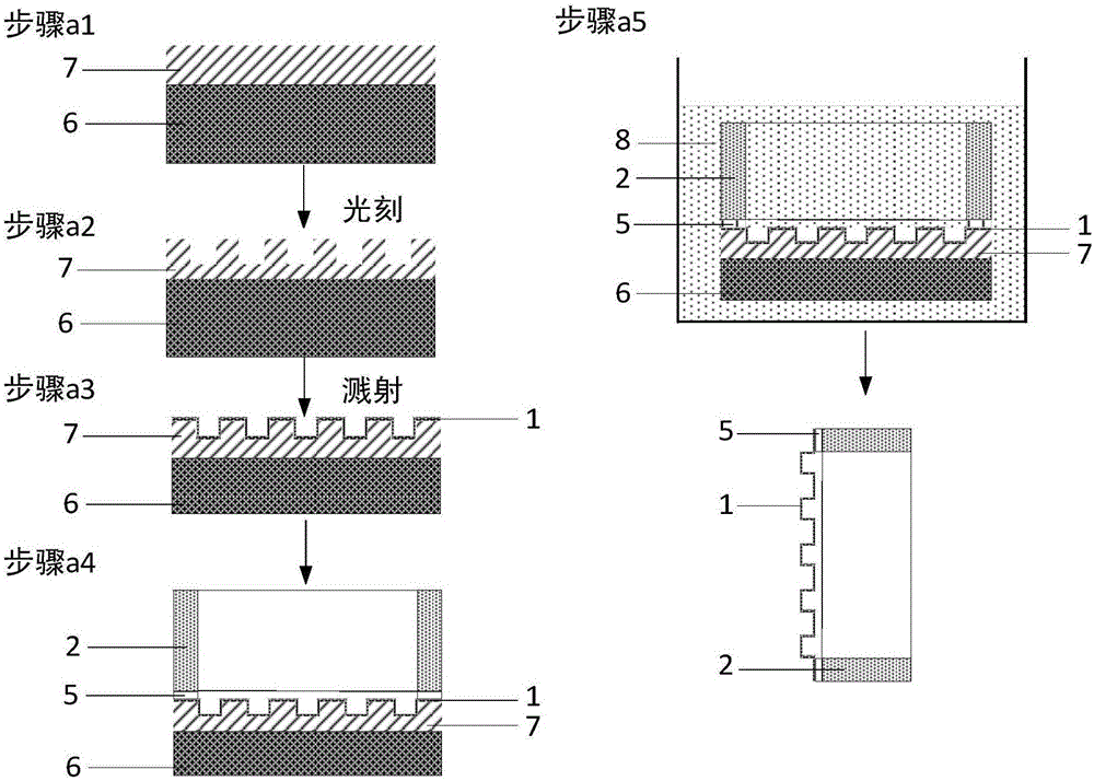
[0047] The optical fiber F-P sound pressure sensor based on the metal pattern film of the present embodiment, on the basis of the specific embodiment 1, further defines its processing method, including the following steps:

[0048] Step a, making metal corrugated film 1;

[0049] Step b, attaching the metal corrugated film 1 to one end surface of the through-cavity sleeve 2 with curing glue 5;

[0050] Step c, insert the ferrule 3 that matches the inner wall of the through-cavity sleeve 2 from the other end face of the through-cavity sleeve 2, and fix it with curing glue 5;

[0051] Step d. Insert the optical fiber 4 whose end surface is polished and smooth from the center of the ferrule 3 , adjust the length of the optical fiber 4 , and fix it with curing glue 5 .


PUM


Abstract

A fiber optic F-P sound pressure sensor based on metal film belongs to the technical field of the sound pressure sensor. The sound pressure sensor comprises a metal corrugated film, a cavity casing, a ferrule and an optical fiber. The metal corrugated film is used as a sound pressure sensitive element, and is bonded with one end face of the cavity sleeve with a cured adhesive, and a ferrule with the inner wall of the cavity casing is inserted from the other end face of the cavity sleeve, and the center of the ferrule is inserted with an end-polished fiber. The cavity sleeve, the ferrule and the fiber set co-axially, and a cure adhesive is used to fix the cavity sleeve and the ferrule, and the cure adhesive is also used to fix the ferrule and the fiber. The fiber optic F-P sound pressure sensor based on metal film is capable of solving the technical problems caused by the diaphragm material or the diaphragm shape.

Description

technical field [0001] The optical fiber F-P sound pressure sensor based on the metal pattern film of the invention belongs to the technical field of sound pressure sensors. Background technique [0002] At this stage, the membrane-type optical fiber F-P sound pressure sensor is vigorously developed due to its advantages of fast response, high sensitivity, simple production, low cost, and no interference from environmental noise. The characteristic of diaphragm type optical fiber F-P sound pressure sensor is that the sensitive diaphragm and the end face of the optical fiber form the F-P cavity. The external sound pressure signal will cause the sensitive diaphragm to vibrate, and then change the cavity length of the F-P cavity, resulting in changes in the reflected light signal. This change can realize the detection of information related to the external sound pressure. [0003] The performance of this type of sound pressure sensor is directly related to the diaphragm. At p...

Claims


Application Information

Patent Timeline
Patent Type & Authority Applications(China)
IPC IPC(8): G01H9/00G02B6/42
CPCG01H9/004G02B6/42
Inventor 金鹏刘彬王艾琳王兴林杰
Owner HARBIN INST OF TECH
Why Eureka
Try Eureka