Non-contact measuring device and method for aerosol mass concentration field

A non-contact measurement and mass concentration technology, applied in the field of laser technology and image processing, can solve the problem of only measuring aerosol mass concentration in local areas

Active Publication Date: 2017-05-31
BEIJING INSTITUTE OF TECHNOLOGYGY
View PDF2 Cites 3 Cited by
  • Summary
  • Abstract
  • Description
  • Claims
  • Application Information

AI Technical Summary

Problems solved by technology

[0003] The purpose of the present invention is to solve the problem that the prior art can only measure the aerosol mass concentration in local areas, and provide a non-contact measurement device and method for the aerosol mass concentration field, which can measure the mass concentration distribution of the aerosol in space

Method used


Image

  • Non-contact measuring device and method for aerosol mass concentration field
  • Non-contact measuring device and method for aerosol mass concentration field
  • Non-contact measuring device and method for aerosol mass concentration field

Examples


Embodiment 1

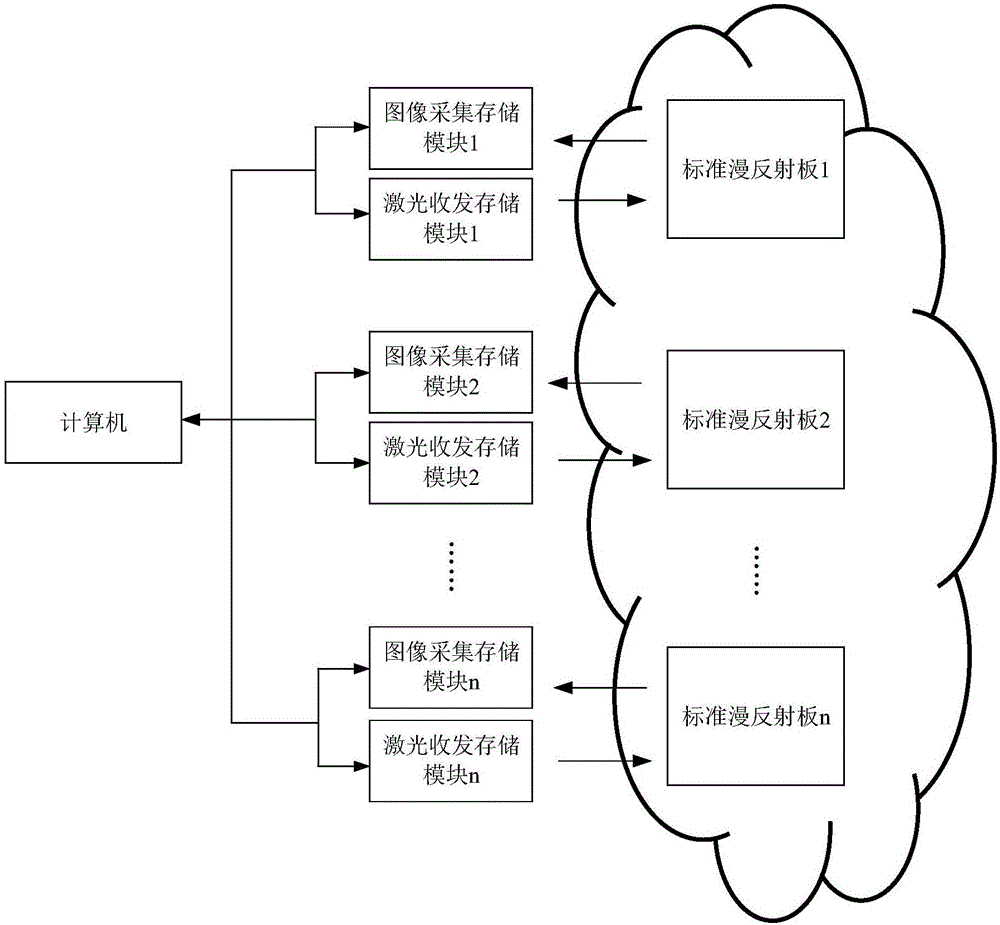
[0034] A non-contact measuring device and method for an aerosol mass concentration field, such as figure 1 As shown, the specific steps are as follows:

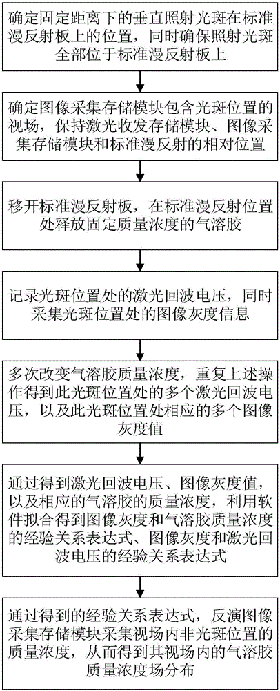
[0035] Step 1. Determine the position of the vertical illumination spot at a fixed distance on the standard diffuse reflection plate, and at the same time ensure that all the illumination spots are located on the standard diffuse reflection;

[0036] Step 2. Determine the field of view of the image acquisition storage module including the spot position, and maintain the relative positions of the laser emitting and receiving components, the image acquisition storage module and the standard diffuse reflection;

[0037] Step 3, remove the standard diffuse reflection plate, and release the aerosol with a fixed mass concentration at the standard diffuse reflection position;

[0038] Step 4. Record the laser echo voltage at the spot position, and collect the image grayscale information at the spot position at the same time;

[00...

Embodiment 2

[0056] (1) In this embodiment, one computer and one set of laser transceiver and storage modules, image acquisition and storage modules and standard diffuse reflectors are used. The model of the semiconductor laser in the laser transceiver storage module is 905D1S3J09UA, and the model of the photodetector is BPX-65. The model of the CCD camera in the image acquisition storage module is DST-918. The signal source generates an excitation signal with a repetition frequency of 1kHz and a pulse width of 20ns. A photographic smoke cake was used as the source of aerosol generation. The laser is emitted through the laser transceiver storage module, and the standard diffuse reflection plate is moved to ensure that the laser spot is vertically irradiated on the standard diffuse reflection plate and all the light spots are located on the standard diffuse reflection plate, keeping the distance between the two unchanged. The spot irradiation position is as Figure 4 shown;

[0057] (2)...


PUM


Abstract

The invention relates to a non-contact measuring device and method for an aerosol mass concentration field and belongs to the fields of laser technologies and image processing technologies. In order to measure mass concentration distribution of aerosol in space, the non-contact measuring device and method enable a laser detecting technology and an image processing technology to be combined. The non-contact measuring method comprises the steps: firstly, utilizing corresponding relation between laser echo voltage of aerosol at the laser radiation position and a gray level image of the laser radiation position to establish empirical relationship expression between image gray level and the laser echo voltage and empirical relationship expression between the image gray level and mass concentration; inverting image gray level of the aerosol at the non-laser-radiation position according to image gray level of the non-laser-radiation position of the aerosol; accordingly obtaining aerosol mass concentration field distribution in a collecting view field of an image collecting and storing module.

Description

technical field [0001] The invention relates to a non-contact measuring device and method for an aerosol mass concentration field, belonging to the technical fields of laser technology and image processing. Background technique [0002] There are sampling and non-sampling methods for measuring aerosol concentration. Sampling methods include filter weighing method, ray absorption method and piezoelectric crystal method, etc.; non-sampling methods include optical method, acoustic method and charge method, among which optical methods include image method, response spectrum method, light transmission method and light scattering method, etc. . Aerosol has the characteristics of wide spatial distribution and uneven concentration distribution. The current aerosol concentration measurement method can only measure the aerosol mass concentration in a local area, and cannot obtain the spatial distribution of the aerosol mass concentration field. Contents of the invention [0003] T...

Claims


Application Information

Patent Timeline
Patent Type & Authority Applications(China)
IPC IPC(8): G01N15/06
CPCG01N15/06G01N2015/0693
Inventor 陈慧敏刘伟博王凤杰马超顾健
Owner BEIJING INSTITUTE OF TECHNOLOGYGY
Why Eureka
Try Eureka