Self-locking float level switch

A floating ball liquid level and switch technology, which is used in liquid level control, non-electric variable control, instruments, etc., can solve the problems of inability to lock, unstable shaking state, affecting the stable work of electrical appliances, and achieve reliable performance and convenience. The effect of promoting use and preventing random changes

Active Publication Date: 2017-05-31
NANJING VOCATIONAL UNIV OF IND TECH
View PDF15 Cites 0 Cited by
  • Summary
  • Abstract
  • Description
  • Claims
  • Application Information

AI Technical Summary

Problems solved by technology

[0004] For this kind of float level switch, the float fluctuates on the surface of the water, and the magnet inside the float fluctuates up and down accordingly. The change of the surrounding magnetic field caused by the movement of the reed switch with the movement of the float causes the above two working states to appear alternately. , the working state of the liquid level switch is an unstable jitter state, which cannot be locked, which will affect the stable operation of the actuator (such as the liquid level motor)

Method used


Image

  • Self-locking float level switch
  • Self-locking float level switch

Examples


Embodiment 1

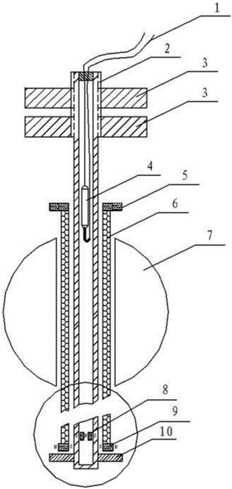
[0022] A self-locking float liquid level switch, including a closed non-magnetic tube 2, a reed switch 4 is arranged inside the non-magnetic tube 2, and two lead wires 1 at the top of the reed switch 4 are control signal lines, and the non-conductive tube 2 is provided with a reed switch 4. The top of the magnetic tube 2 is provided with a thread and two hexagonal nuts 3 for installation, which are used to install the self-locking float level switch.

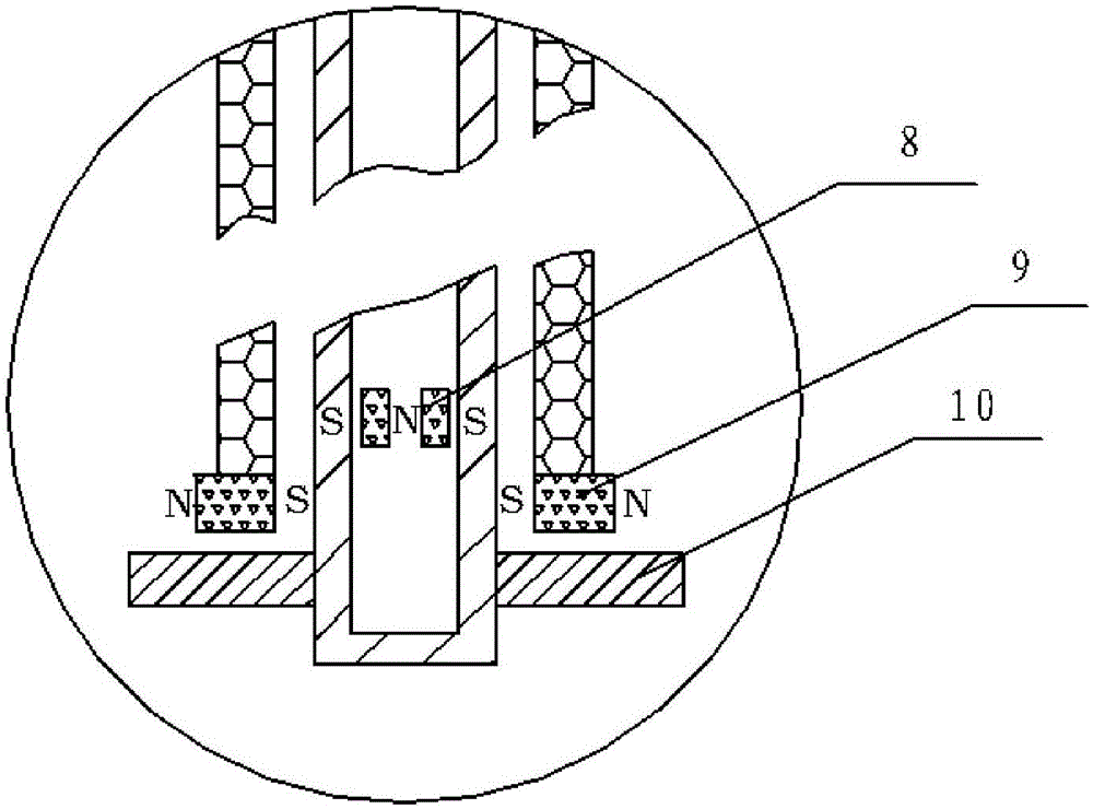
[0023] The non-magnetic tube 2 is provided with a cylindrical passive buoy 6 that can float up and down along the non-magnetic tube 2. The specific gravity of the material used for the buoy 6 is not greater than that of the liquid. The stopper 10 for limiting the position in the direction; the cylindrical passive buoy 6 is covered with a buoy 7 which slides and fits with the buoy 6 .

[0024] The two ends of the cylindrical passive buoy 6 are respectively provided with an upper magnetic limiting plate 5 and a lower magnetic limi...


PUM


Abstract

The invention discloses a self-locking float level switch. The self-locking float level switch comprises a non-magnetic pipe, a reed switch, a cylindrical passive float barrel, a float ball, a retainer, an upper magnetic limiting plate, a lower magnetic limiting plate and inner magnets. The cylindrical passive float barrel externally sleeves the non-magnetic pipe, the float ball externally sleeves the cylindrical passive float barrel, the retainer is arranged at the bottom end of the non-magnetic pipe, the upper magnetic limiting plate and the lower magnetic limiting plate are arranged at upper and lower ends of the cylindrical passive float barrel respectively, and the inner magnets are detachably arranged in the non-magnetic pipe. An annular magnet is hermetically arranged in the upper magnetic limiting plate, and the upper magnetic limiting plate is in positional correspondence to the reed switch under a contacted state of the bottom of the float barrel and the retainer. Independent magnets are arranged in the lower magnetic limiting plate, and opposite poles of the inner magnets in the non-magnetic pipe and the independent magnets in the lower magnetic limiting plate are identical in polarity. The self-locking float level switch has advantages that a self-locking effect can be achieved; due to a completely stable float magnetic field system, the float ball is prevented from fluctuating along with water level, magnetic field random variation is prevented, peripheral control circuit simplification is realized, and stability in operation of an execution electric appliance is achieved.

Description

technical field [0001] The invention relates to a liquid level detection device, in particular to a self-locking float liquid level switch. Background technique [0002] The liquid level float switch is a simple structure, easy to use, safe and reliable liquid level detection tool. It uses a magnetic reed switch as the contact point. Based on the principle of buoyancy, the float with magnetic components is used to drive the lower limit with the rise and fall of the liquid level. The dry reed switch at the upper limit position opens and closes, and outputs ON or OFF contact signals to realize the start and stop of the pump motor, solenoid valve or other electrical equipment, so as to achieve automatic control of the high and low liquid level in the container. [0003] The current float level switch in the liquid level control system has a specific structure of installing a magnetic element dry reed switch in a closed non-magnetic tube. When the surrounding magnetic field chan...

Claims


Application Information

Patent Timeline
Patent Type & Authority Applications(China)
IPC IPC(8): G05D9/04
CPCG05D9/04
Inventor 贺炜王红军邓滨
Owner NANJING VOCATIONAL UNIV OF IND TECH
Why Eureka
Try Eureka