Power grid structure optimization method capable of reducing transmission loss and relieving voltage sag

A technology of voltage sag and power grid structure, applied in instruments, data processing applications, forecasting, etc., can solve problems such as affecting the static safety and stability of the system, affecting the transient safety and stability, and not considering branch faults.

Inactive Publication Date: 2017-05-31
XIAN UNIV OF SCI & TECH
View PDF4 Cites 6 Cited by
  • Summary
  • Abstract
  • Description
  • Claims
  • Application Information

AI Technical Summary

Problems solved by technology

In terms of voltage sag control, the power supply side can alleviate the voltage sag from the perspective of optimizing the grid structure. The grid structure affects the static security and stability of the system and also affects the transient security and stability. Research on the Effects of Changes on the Transient Stability of Power Systems" studies this problem. In order to solve the above problems, there are also many research results. For example, Tao Shun, Xiao Xiangning, etc. published in "China The article "Random Prediction and Mitigation Measures for Voltage Sag in Multi-structure and Multi-Network Structure System" on pages 30-34 of "Electric Power" proposes that an effective measure to alleviate voltage sag is the implementation of multi-slice and multi-power sources in the distribution network The closed-loop design of open-loop power su

Method used


Image

  • Power grid structure optimization method capable of reducing transmission loss and relieving voltage sag
  • Power grid structure optimization method capable of reducing transmission loss and relieving voltage sag
  • Power grid structure optimization method capable of reducing transmission loss and relieving voltage sag

Examples


Embodiment Construction

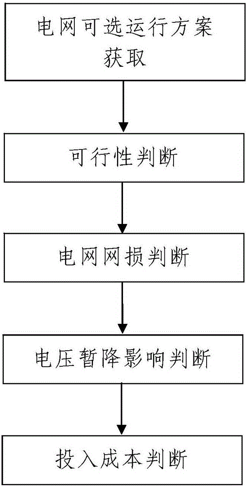
[0061] Such as figure 1 A power grid structure optimization method for reducing network loss and alleviating voltage sag is shown, including the following steps:

[0062] Step 1. Obtaining the optional operation plan of the power grid: According to whether parallel capacitors are installed on each bus in the power grid to be optimized and the capacity of the installed parallel capacitors, and whether switches are installed on each branch and the state of the installed switches, the power grid to be optimized is obtained All optional operating schemes for ;

[0063] Each of the optional operation schemes includes the shunt capacitor configuration information of each bus in the grid to be optimized and the switch setting information of each branch, and the shunt capacitor configuration information of each bus includes whether parallel capacitors are installed on the bus. The capacity of the capacitor and the installed parallel capacitor, the switch setting information of each b...


PUM


Abstract

The invention discloses a power grid structure optimization method capable of reducing transmission loss and relieving voltage sag, comprising the following steps: first, acquisition of optional operation schemes of a power grid: acquiring all optional operation schemes according to the condition whether parallel capacitors are installed on respective buses in a to-be-optimized power grid, capacity of the installed parallel capacitors, the condition whether switches are installed on respective branches, and states of the installed switches; second, feasibility determination; third, determination of transmission loss of the power grid: screening operation schemes with low transmission loss; fourth, determination on influence of voltage sag: 401, calculating voltage sag evaluation indexes of the power grid, 402, determining a configuration scheme with low voltage sag influence; and fifth, investment cost determination: 501, calculating investment cost, 502, determining an optimized operation scheme. The power grid structure optimization method disclosed by the invention has the advantages of simple method steps, reasonable design, convenience for implementation, good using effect, reduced transmission loss, relieved voltage sag, economical configuration of the parallel capacitors and capability of realizing safety operation and economical operation of the power grid.

Description

technical field [0001] The invention belongs to the technical field of power grid optimization operation, and in particular relates to a power grid structure optimization method for reducing network loss and alleviating voltage sag. Background technique [0002] Currently. With the development of modern industry, available resources are constantly decreasing, and energy conservation has been gradually recognized and valued by people. Power systems employ various methods to reduce network losses. The line loss rate of major western industrial countries is roughly 5% to 8%, and that of our country is about 9%, which is still far behind compared with developed countries. It is a long-term task for the power system to continuously reduce the network loss of the power system and improve the economic efficiency of the power system operation. [0003] With the increasing proportion of sensitive loads in industrial loads, the problem of voltage sag is becoming more and more serio...

Claims


Application Information

Patent Timeline
IPC IPC(8): G06Q10/04G06Q50/06
CPCG06Q10/04G06Q50/06Y02E40/70Y04S10/50
Inventor 马莉
Owner XIAN UNIV OF SCI & TECH
Why Eureka
Try Eureka