Liquid flow box for liquid flow battery and single battery thereof

A technology of liquid flow battery and liquid flow frame, which is applied in the direction of fuel cells, circuits, electrical components, etc., and can solve the problems of affecting the overall performance and operating costs of the system, burning out the isolation film, conductive plastic plate electrodes, and inability to collect single-cell voltage, etc. problems, to achieve the effect of promoting large-scale batch production and application, high installation success rate, and convenient installation

Inactive Publication Date: 2017-05-31
SUZHOU JIURUN ENERGY TECH
View PDF6 Cites 5 Cited by
  • Summary
  • Abstract
  • Description
  • Claims
  • Application Information

AI Technical Summary

Problems solved by technology

[0004] In the existing patented technology of the liquid flow frame for the flow battery, firstly, there is no liquid flow frame with a long-term working temperature higher than 70°C; secondly, there is internal leakage between the liquid flow frames on both sides of the electrode, resulting in part of the electrolyte not passing through the electrode. , also known as electrode internal leakage, and the effect of electrolyte flow sharing is poor, which directly affects the performance of the stack, and even causes local overheating to burn out the isolation film, conductive plastic plate and electrodes, thereby damaging the stack and affecting the overall performance of the system macroscopically and operating costs; again, the direct contact between the liquid flow frame and the liquid flow frame will cause overpressure to the isolation membrane sandwiched between the liquid flow frames, which may cause direct damage or fatigue damage to it; in addition, the liquid flow frame does not The external tap of the conductive bipolar plate is set, and the voltage of each single cell of the stack cannot be collected

Method used


Image

  • Liquid flow box for liquid flow battery and single battery thereof
  • Liquid flow box for liquid flow battery and single battery thereof
  • Liquid flow box for liquid flow battery and single battery thereof

Examples


Embodiment Construction

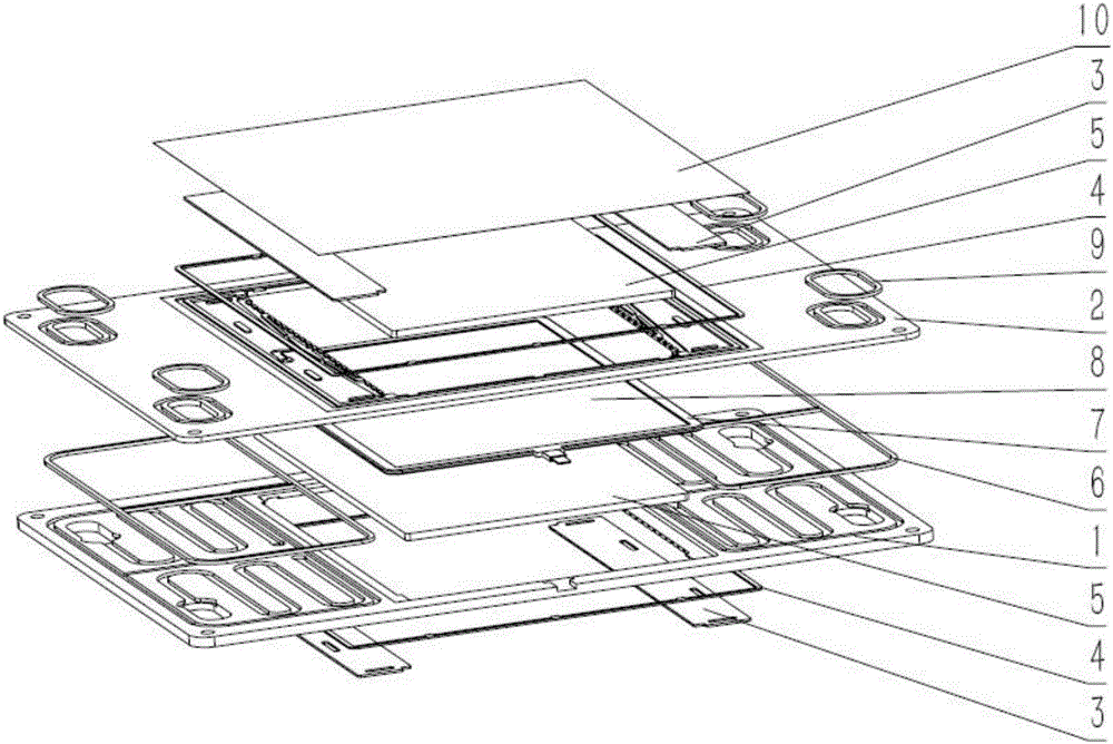
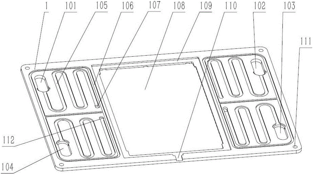
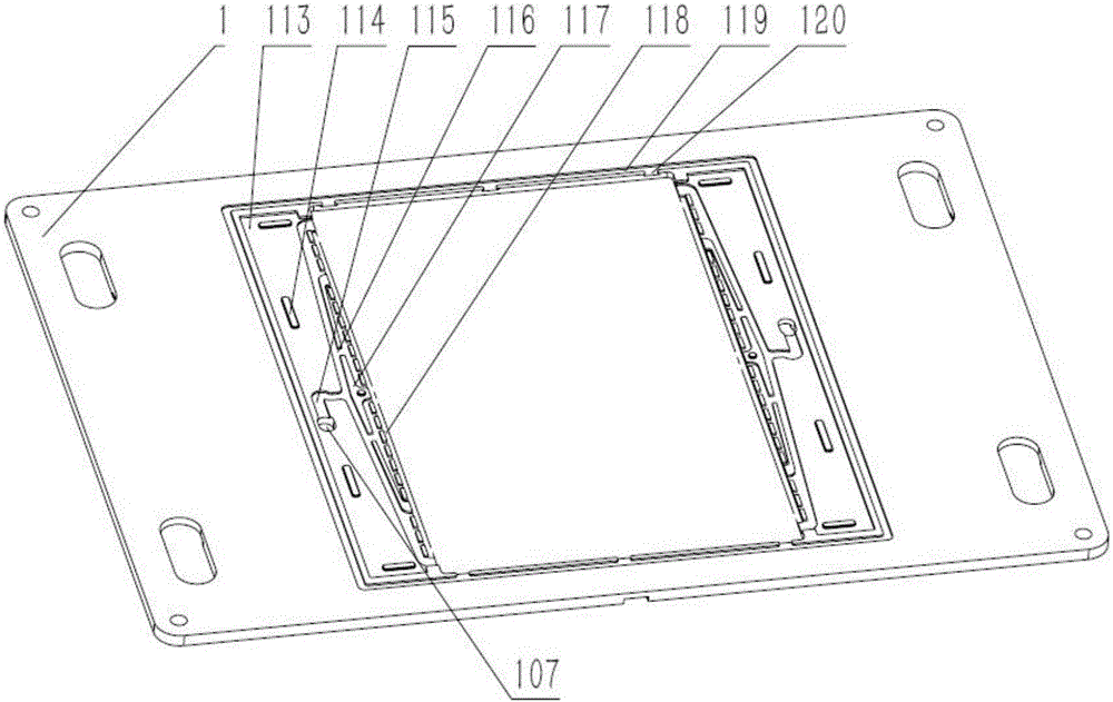
[0034]In the existing patented technology, there is no liquid flow frame with a working temperature higher than 70 °C, and to solve the problem of internal leakage between the electrodes and the leakage between the liquid flow frame; secondly, there is no isolation film protection tank, which is easy to damage or damage the isolation film; again , the liquid flow frame is not equipped with a conductive bipolar plate for external taps, and the voltage of each single cell of the stack cannot be collected. In addition, the flow uniformity of the liquid flow frame in the existing patent is not as good as that of the present invention. The flow uniformity channel of the present invention adopts a "eight"-shaped structure, and is equipped with a flow balance block and a flow uniformity groove, and the flow uniformity is greater than that of the present invention. 99%; the liquid flow frame of the present invention is provided with positioning pin holes, which is convenient for instal...


PUM


Abstract

The invention discloses a liquid flow box for a liquid flow battery and a single battery thereof. The liquid flow box comprises a positive liquid flow box and a negative liquid flow box; two centro-symmetric positive shared flow channels and two centro-symmetric negative shared flow channels are respectively formed in four corners on the front side of the positive liquid flow box; centro-symmetric isolation membrane cover plate grooves on the left and the right are respectively formed in the reverse side of the positive liquid flow box and the front side of the negative liquid flow box; a first overturn hole, a secondary flow limiting channel, a splayed flow equalizing channel, a flow equalizing baffle table and a flow equalizing groove are sequentially formed in each of the isolation membrane cover plate grooves. The liquid flow box for the liquid flow battery, disclosed by the invention, has the advantages of being high in electric pile mounting success rate, free from internal and external leakage, convenient to mount, long in service life, convenient to maintain and the like, effectively protects an isolating membrane and can acquire the battery voltage and greatly promote the large-scale mass production and the application of the liquid flow battery.

Description

technical field [0001] The invention belongs to the technical field of flow batteries, and in particular relates to a flow frame for a flow battery and a single battery thereof. Background technique [0002] The country's "Thirteenth Five-Year Plan" proposes to promote the energy revolution and strengthen the construction of energy storage. Liquid phase fluid energy storage battery, referred to as liquid flow battery, is an efficient and reliable energy storage device, which can store electrical energy in the electrolyte solution when charging, and release the stored energy when discharging. As one of the core technologies of the new generation of smart grid, the application of flow batteries can realize the continuous and stable output of wind power and photovoltaic power, and can also balance the power supply and load operation of the traditional grid, effectively improving the quality of power and increasing the utilization rate. Compared with other energy storage techno...

Claims


Application Information

Patent Timeline
IPC IPC(8): H01M8/0273H01M8/0258
CPCH01M8/0258H01M8/0273Y02E60/50
Inventor 王聪康马志啟郭煌田清谭长永
Owner SUZHOU JIURUN ENERGY TECH
Why Eureka
Try Eureka