
A control method for a cooling system of an electrical cabinet

A heat dissipation system and control method technology, applied in the direction of electrical components, cooling/ventilation of substation/switchgear, substation/switch layout details, etc., can solve problems such as short circuit, affecting normal operation of electrical components, high cost, etc.

Inactive Publication Date: 2019-03-08
浙江科源电器有限公司
View PDF6 Cites 0 Cited by
  • Summary
  • Abstract
  • Description
  • Claims
  • Application Information

AI Technical Summary

Problems solved by technology

[0002] The electrical cabinet is a commonly used equipment. The components in the electrical cabinet will heat up after long-term use, which will easily cause the temperature in the electrical cabinet to rise. Excessive temperature will affect the normal operation of the electrical components. Therefore, it is necessary to dissipate heat from the electrical cabinet. Air conditioner or fan to achieve; using air conditioner will cost more
[0003] On the other hand, the temperature in the electrical cabinet should not be too low. When the temperature in the electrical cabinet is too low, the air cannot hold a large amount of moisture, and the precipitated air moisture will condense on the electrical components, terminal blocks or box walls, causing Short circuit phenomenon, endangering the safe operation of power equipment
In order to solve this problem, a heating dehumidifier is usually installed in the electrical cabinet. The heating dehumidifier is mainly used to increase the temperature in the electrical cabinet, but it is not used at ordinary times, because the air with a higher temperature can contain more moisture, thus Prevent water vapor from directly condensing on the electrical equipment and terminal blocks in the box, and prevent accidents such as flashover and short circuit. However, each electrical cabinet is equipped with a heating dehumidifier, which not only increases the cost, but also occupies the installation space of the equipment. This approach is actually not ideal

Method used


Image

  • A control method for a cooling system of an electrical cabinet
  • A control method for a cooling system of an electrical cabinet
  • A control method for a cooling system of an electrical cabinet

Examples


Embodiment 1

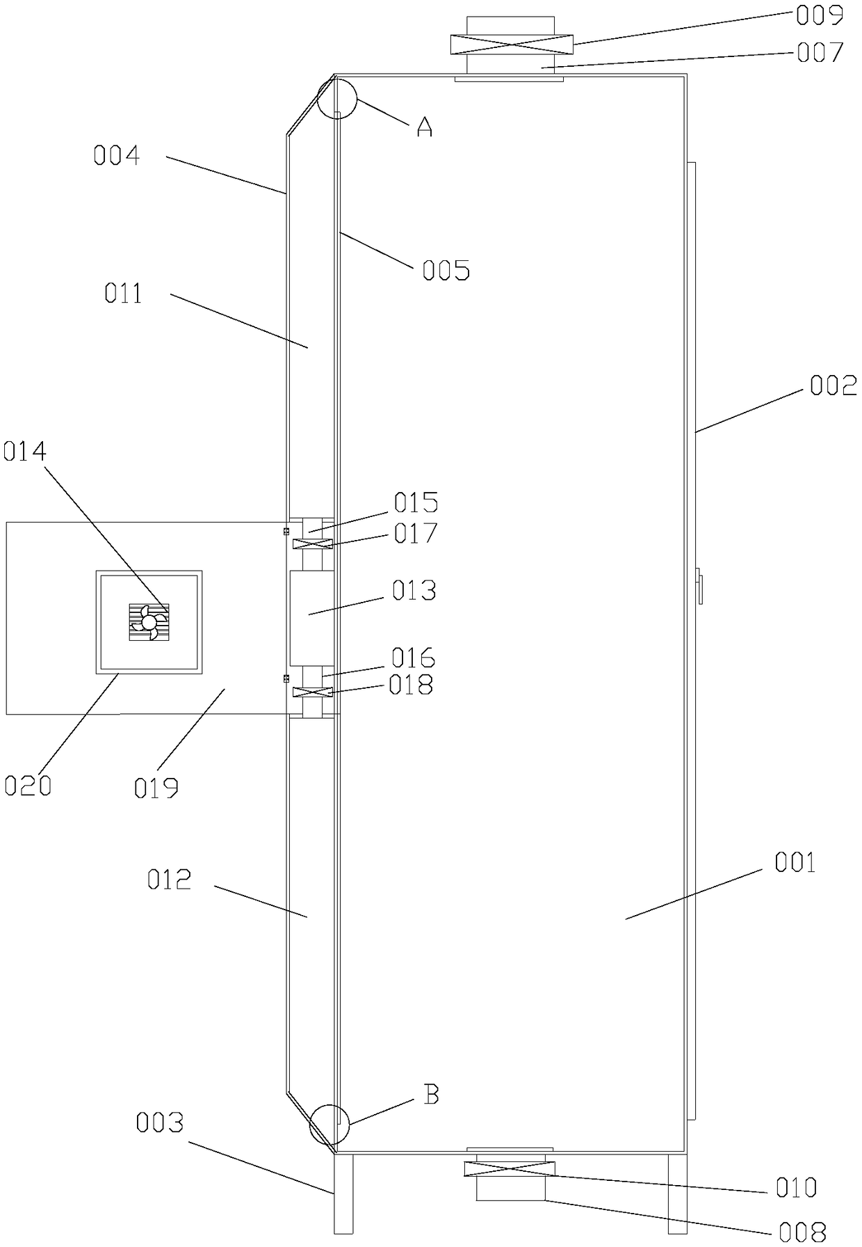
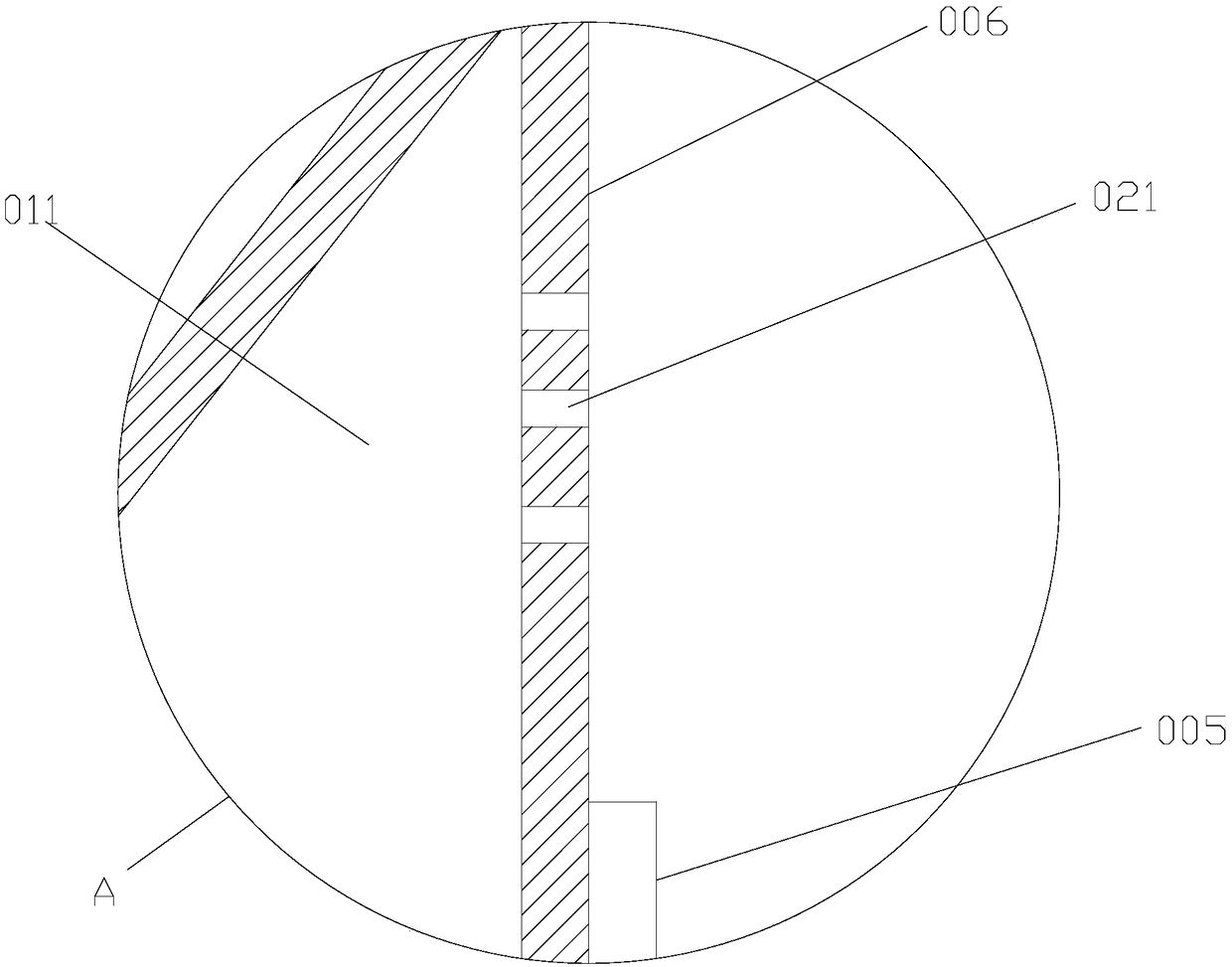
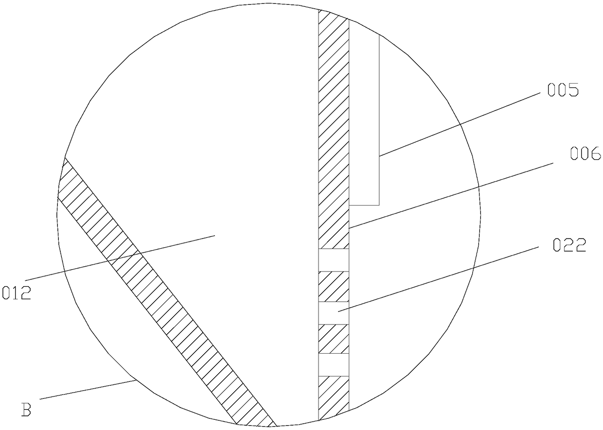
[0031] Such as figure 1 , 2 , 3, the electrical cabinet described in this embodiment includes a cabinet body 001, a cabinet door 002 hinged on the front of the cabinet body 001, a cabinet foot 003 below the cabinet body 001, and a backpack cavity 004 on the back of the cabinet body 001. The back plate 006 of 001 is provided with an electrical component mounting plate 005, and the electrical component mounting plate 005 is separated from the top and bottom of the back plate 006 by a certain distance (this distance is for setting the upper ventilation hole 021 and the lower ventilation hole described below. Hole 022, this section distance can be 5-10 centimetre), is respectively provided with upper ventilation pipe 007 and lower ventilation pipe 008 on the cabinet body 001 top and bottom, is respectively provided with upper ventilation pipe 007 and lower ventilation pipe 008 Valve 009 and lower ventilation valve 010, the upper part of the backpack cavity 004 is a sealed upper w...

Embodiment 2

[0034] Such as Figure 4 , 5 , 6, the heat dissipation system of the electrical cabinet described in this embodiment includes several electrical cabinets 000 arranged side by side on the floor 101 of the power distribution room 100 (the specific number is subject to actual application), and the power distribution room 100 The upper part is provided with a suspended ceiling 102, and a ventilation window 103 is provided above the suspended ceiling 102. A basement 104 is provided below the floor 101 of the power distribution room 100, and an air duct 105 is provided above the electrical cabinet 000 (the air duct 105 is made of thin iron sheet or a rectangular parallelepiped air duct made of stainless steel), the top of the air duct 105 is connected with an exhaust pipe 106 extending to the top of the suspended ceiling 102, and an exhaust valve 107 is arranged on the exhaust pipe 106; Blower 108, described blower 108 is communicated with described basement 104 through blower pipe...


PUM


Abstract

The invention discloses an electrical cabinet. An upper ventilation pipe and a lower ventilation pipe are arranged on a cabinet body, an upper air chamber is arranged at an upper part of a back package cavity of the cabinet body, a lower air chamber is arranged at a lower part of the back package cavity, an air outlet chamber is arranged at the center of the back package cavity, an air outlet door is hinged with the middle part of the back package cavity, an exhaust fan is arranged on the air outlet door, and an upper ventilation hole and a lower ventilation hole are formed in a back plate. The invention also discloses a heat dissipation system of the electrical cabinet. A basement is arranged below a ground plate of a power distribution room, an air duct is arranged above the electrical cabinet, an exhaust pipe is connected with the top of the air duct, an air blower is arranged outside the power distribution room, a hot air cabinet is fixedly arranged on a side surface of the air duct, upper air holes are formed in a bottom surface of the air duct and are in one-to-one correspondence to the electrical cabinets, and lower air holes are formed in the ground plate of a power distribution cabinet and are in one-to-one correspondence to the electrical cabinets. The electrical cabinet has the advantages that hot air can be borrowed from the electrical cabinet aside to increase the temperature of the electrical cabinet when the temperature of the electrical cabinet is excessively low, the condensation-preventing cost is lower, meanwhile, independent or centralized heat dissipation can be achieved, and the heat dissipation effect is good.

Description

technical field [0001] The invention relates to the field of electric equipment, in particular to an electric cabinet, a cooling system for the electric cabinet and a control method thereof. Background technique [0002] The electrical cabinet is a commonly used equipment. The components in the electrical cabinet will heat up after long-term use, which will easily cause the temperature in the electrical cabinet to rise. Excessive temperature will affect the normal operation of the electrical components. Therefore, it is necessary to dissipate heat from the electrical cabinet. Air conditioners or fans to achieve; the use of air conditioners is more costly. [0003] On the other hand, the temperature in the electrical cabinet should not be too low. When the temperature in the electrical cabinet is too low, the air cannot hold a large amount of moisture, and the precipitated air moisture will condense on the electrical components, terminal blocks or box walls, causing Short ci...

Claims


Application Information

Patent Timeline
Patent Type & Authority Patents(China)
IPC IPC(8): H02B1/56
CPCH02B1/565
Inventor 高明
Owner 浙江科源电器有限公司
Learn More