Self-powered circuit and wearable equipment with same
A self-powered, circuit technology, applied in battery circuit devices, circuit devices, collectors, etc., can solve problems such as frequent charging times, poor user experience, limited battery capacity, etc., to improve user experience, reduce charging frequency, and extend battery life the effect of time
- Summary
- Abstract
- Description
- Claims
- Application Information
AI Technical Summary
Problems solved by technology
Method used
Image

Examples
Embodiment 1
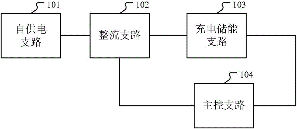
[0022] figure 1 It is a schematic structural diagram of a self-powered circuit according to an embodiment of the present invention, see figure 1 , the circuit includes: a self-power supply branch 101, a rectification branch 102, a charging energy storage branch 103 and a main control branch 104;
[0023] The self-power supply branch 101 is used to convert kinetic energy into electric energy, and transmit the electric energy to the rectification branch;
[0024] The rectification branch 102 is used to rectify the electric energy generated by the self-power supply branch to obtain a stable value of direct current, and transmit the direct current to the main control branch according to the instructions of the main control branch. control branch or the charging energy storage branch; this branch specifically includes: a rectification and filtering branch, a voltage stabilization branch and an output control branch; the rectification and filtering branch is used to generate The a...
Embodiment 2
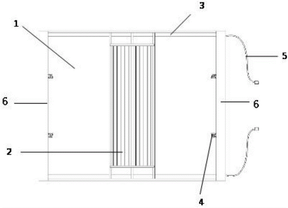
[0028] Based on the above examples, such as figure 2 As shown, it is a schematic diagram of the structure of the self-supply branch in the self-supply circuit in the technical solution of the present invention; the self-supply branch includes: two magnets 1, movers 2, two guide rails 3, spring sets 4, outer frames 6 and wires 5;
[0029] The two magnets 1 are arranged opposite to each other to form a vertical magnetic field;
[0030] The two guide rails 3 are relatively arranged in the horizontal direction, and the two ends of the mover 2 are respectively slidably connected to the two guide rails 3; the guide rails have good electrical conductivity and low friction.
[0031] The mover 2 slides in the horizontal direction along the direction of the two guide rails 3, and cuts the magnetic field lines of the vertical magnetic field formed by the two magnets 1; the mover 2 is composed of at least two enameled wires connected in parallel. The mover 2 will slide on the guide rai...
Embodiment 3
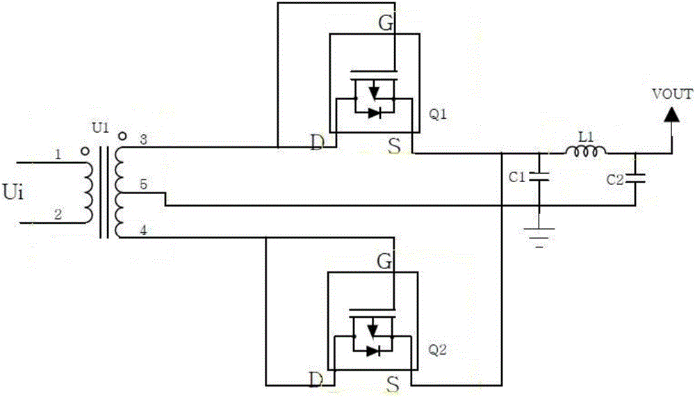
[0037] like image 3 As shown, it is a rectification and filtering shunt circuit diagram of a rectification branch of a self-powered circuit in the technical solution of the present invention; the circuit includes: a first transformer U1, a first switching tube Q1, a second switching tube Q2, and a first capacitor C1 , the first inductor L1 and the second capacitor C2;
[0038] The input terminal 1 and input terminal 2 of the same name of the first transformer U1 are connected to the output terminal of the self-power supply branch, that is, the wire 5;
[0039] The output terminal 3 of the same name of the first transformer U1 is connected to the drain and gate connection terminal of the first switching tube Q1;
[0040] The output terminal 4 of the first transformer U1 is connected to the drain and gate connection terminal of the second switching tube Q2;
[0041] The output terminal 5 of the first transformer U1 is grounded;
[0042] The source of the first switching tube...
PUM
 Abstract
Description
Claims
Application Information
 - R&D
- Intellectual Property
- Life Sciences
- Materials
- Tech Scout
- Unparalleled Data Quality
- Higher Quality Content
- 60% Fewer Hallucinations
Browse by: Latest US Patents, China's latest patents, Technical Efficacy Thesaurus, Application Domain, Technology Topic, Popular Technical Reports.
© 2025 PatSnap. All rights reserved.Legal|Privacy policy|Modern Slavery Act Transparency Statement|Sitemap|About US| Contact US: help@patsnap.com