Oil-immersion cooling structure and cooling method for hub motor with dynamic adjustable oil quantity in cavity

A hub motor and cooling structure technology, applied in the direction of electric components, cooling/ventilation devices, electrical components, etc., can solve the problems of limited heat dissipation effect of heat conduction oil, affecting motor efficiency, slow rotor speed, etc.

Active Publication Date: 2017-05-31
GUANGDONG HI 1 NEW MATERIALS TECH RES INST CO LTD
View PDF5 Cites 4 Cited by
  • Summary
  • Abstract
  • Description
  • Claims
  • Application Information

AI Technical Summary

Problems solved by technology

However, in this way, considering the resistance of oil to the rotation of the rotor, adding too much oil will affect the efficiency of the motor. Only a small amount of heat transfer oil can be added, and the oil will be thrown to the motor stator and shell by the rotation of the rotor to dissipate heat. The heat dissipation effect of the running motor is better, and the hub motor generates about 3 times the heat under the normal operating condition when the hub motor is running at a low speed or stalled at a climbing speed. At this time, the rotor rotates slowly or does not rotate, and heat transfer oil deposits At the bottom of the motor oil guide chamber, the heat dissipation effect of the heat conduction oil is very limited

Method used


Image

  • Oil-immersion cooling structure and cooling method for hub motor with dynamic adjustable oil quantity in cavity
  • Oil-immersion cooling structure and cooling method for hub motor with dynamic adjustable oil quantity in cavity

Examples


Embodiment 1

[0020] Embodiment 1: An oil-immersed cooling structure with dynamically adjustable oil volume in the hub motor cavity.

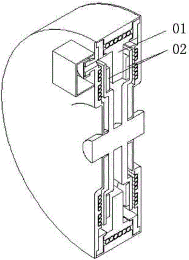
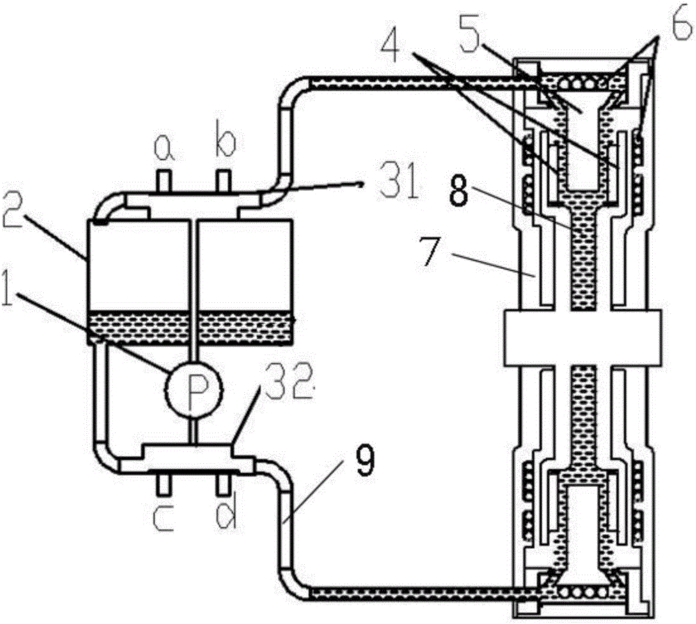
[0021] refer to figure 2 As shown, a dynamic adjustable oil volume immersion oil cooling structure in the hub motor cavity, including: a motor casing 7; a stator coil 5 installed inside the motor casing 7; and a stator coil 5 installed inside the motor casing 7 and capable of rotating The rotor 4; the water cooling jacket 6 is installed between the motor casing 7 and the stator coil 5, the oil guide chamber 8 is arranged between the stator coil 5 and the rotor 4, and the upper end of the oil guide chamber 8 passes through the oil guide pipe 9 Connected to the outlet of the oil passage of the first reversing valve 31, the inlet of the oil passage of the first reversing valve 31 is connected to the oil storage box 2 through the oil guide pipe 9; the lower end of the oil guide chamber 8 is connected to the The outlet of the oil passage of the second reversing...

Embodiment 2

[0026] Embodiment 2: A method for immersion oil cooling with dynamically adjustable oil volume in the hub motor cavity.

[0027] The present invention also provides a cooling method based on the oil immersion cooling structure with dynamically adjustable oil volume in the hub motor cavity in Embodiment 1, which specifically includes the following steps:

[0028] S1. When the motor starts from standstill, stalls or climbs slowly, the speed detector detects that the running speed of the rotor 4 is lower than the set value, the oil pump 1 starts, and the c-position conduction port of the second reversing valve 32 and the first The b-position conduction port of the reversing valve 31 is conducted, the a-position conduction port of the first reversing valve 31 and the d-position conduction port of the second reversing valve 32 are closed, and the oil pump 1 draws oil from the oil storage box 2 , pumped into the oil guide chamber 8 of the motor, when the liquid level detector detect...


PUM


Abstract

The invention provides an oil-immersion cooling structure for a hub motor with dynamic adjustable oil quantity in a cavity. The oil-immersion cooling structure comprises a motor shell, a stator coil mounted on the inner side of the motor shell, and a rotor mounted on the inner side of the motor shell and capable of rotating around the stator coil; a water cooling sleeve is mounted between the motor shell and the stator coil; an oil guiding cavity is formed between the stator coil and the rotor; the upper end and the lower end of the oil guiding cavity are connected to oil path outlets of a first reversing valve and a second reversing valve through oil guiding pipes respectively; oil path inlets of the first reversing valve and the second reversing valve are connected to an oil storage box through the oil guiding pipes; and the first reversing valve and the second reversing valve are connected through an oil pump. The invention also provides an oil-immersion cooling method for the hub motor with dynamic adjustable oil quantity in the cavity. Intelligent dynamic adjustment can be performed according to the operating working conditions of the motor, and heat dissipation requirement of the motor operation in all working conditions can be satisfied; and in addition, relatively high barrier to rotor operation caused by heat conducting oil in the heat dissipation process also can be avoided.

Description

technical field [0001] The invention belongs to the technical field of motor cooling, and in particular relates to an oil immersion cooling structure and cooling method with a dynamically adjustable oil volume in a wheel hub motor cavity. Background technique [0002] With the development of new energy electric vehicles and hybrid technology, compact and efficient in-wheel motor drive methods are gradually becoming popular. The pursuit of extreme vehicle power performance leads to higher and higher power in-wheel motors, so the waste heat generated by the motors increases accordingly (total 3%-5% of the power), if the waste heat cannot be effectively dissipated into the environment in time, it will cause the internal heat of the motor to accumulate and generate high temperature. If the internal temperature of the hub motor is too high, the insulation of the coil will be damaged, and the permanent magnet will be irreversibly demagnetized, etc. As a result, this will greatly r...

Claims


Application Information

Patent Timeline
Patent Type & Authority Applications(China)
IPC IPC(8): H02K9/19
CPCH02K9/19
Inventor 王伟史忠山李雪
Owner GUANGDONG HI 1 NEW MATERIALS TECH RES INST CO LTD
Why Eureka
Try Eureka