

Ultra-wideband indoor positioning method
An indoor positioning and ultra-broadband technology, applied in measurement devices, instruments, surveying and navigation, etc., can solve the problems of time synchronization that cannot be completely solved, the time resolution is not compensated, and the number of users is limited, and achieves high clock synchronization accuracy. The effect of improving accuracy and high positioning accuracy
- Summary
- Abstract
- Description
- Claims
- Application Information
AI Technical Summary
Problems solved by technology
Method used
Image

Examples
specific Embodiment 1
[0054] Specific embodiment 1. Static experiment under line-of-sight environment
[0055] The preferred ultra-wideband indoor positioning hardware chip of the present invention is DWM1000, which has the function of receiving and sending ultra-wideband signals, can realize wireless data transmission in the process of signal exchange, and can provide receiving time stamps and sending time stamps, time resolution is 1 / (128×499.2×10 6 )Second.
[0056] The number of base stations is preferably 4 or more.
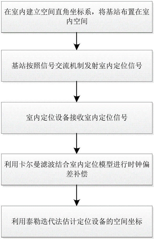
[0057] The specific implementation steps of the inventive method are as follows:
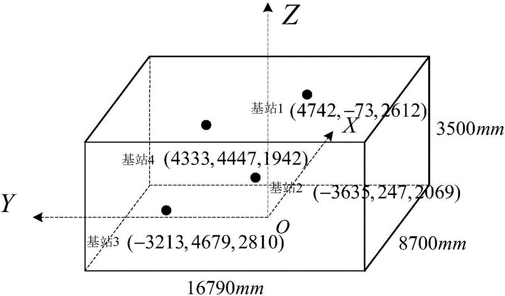
[0058] Step 1: First, establish a space rectangular coordinate system indoors. Arrange 4 base stations at fixed positions indoors, making the 4 base stations non-coplanar. Select the base station close to the center of the room as the main base station, and record it as base station 1, and record the rest of the base stations as base station 2~base station 4, measure and record the coordinates of...
specific Embodiment 2
[0162] Specific embodiment 2. Indoor dynamic positioning
[0163] In the indoor dynamic positioning experiment, the user walks indoors with the positioning device, and other conditions and steps are consistent with the static test in the first embodiment.
[0164] The output trajectory of the system in the horizontal plane is as follows: Figure 15 As shown, the coordinate values output by the system are as follows Figure 16a , Figure 16b , Figure 16c shown. The system can realize accurate indoor three-dimensional positioning.
[0165] The effectiveness of the method of the present invention is verified through indoor static positioning experiments and indoor dynamic positioning experiments.
PUM
 Abstract
Description
Claims
Application Information