
A kind of active industrial flue gas final purification method

An industrial flue gas, active technology, applied in chemical instruments and methods, separation methods, gas treatment and other directions, can solve the problems of weak demineralization ability, low demisting efficiency, influence of demisting stability, etc., to reduce pollution, The effect of high flue gas purification efficiency

Inactive Publication Date: 2019-11-12
符朝伟 +1
View PDF9 Cites 0 Cited by
  • Summary
  • Abstract
  • Description
  • Claims
  • Application Information

AI Technical Summary

Problems solved by technology

[0006] However, the currently used demisters are all passive, with low demist efficiency and dust accumulation. With the increase of dust accumulation, the demist efficiency will be even lower, resulting in weaker and weaker desalination capabilities.
In addition, because the demister adopts a passive method of demisting, the demisting stability is seriously affected by the flue gas flow rate, and the demisting effect is not ideal because the flue gas flow rate is unstable.
[0007] For pollutants such as nitrogen oxides, sulfur dioxide, and dust remaining in industrial flue gas, the existing industrial flue gas final purification technology has not yet been involved. Therefore, it is urgent to fill this technical gap to further reduce the impact of industrial flue gas on the environment. the dirt

Method used


Image

  • A kind of active industrial flue gas final purification method
  • A kind of active industrial flue gas final purification method
  • A kind of active industrial flue gas final purification method

Examples


Embodiment 1

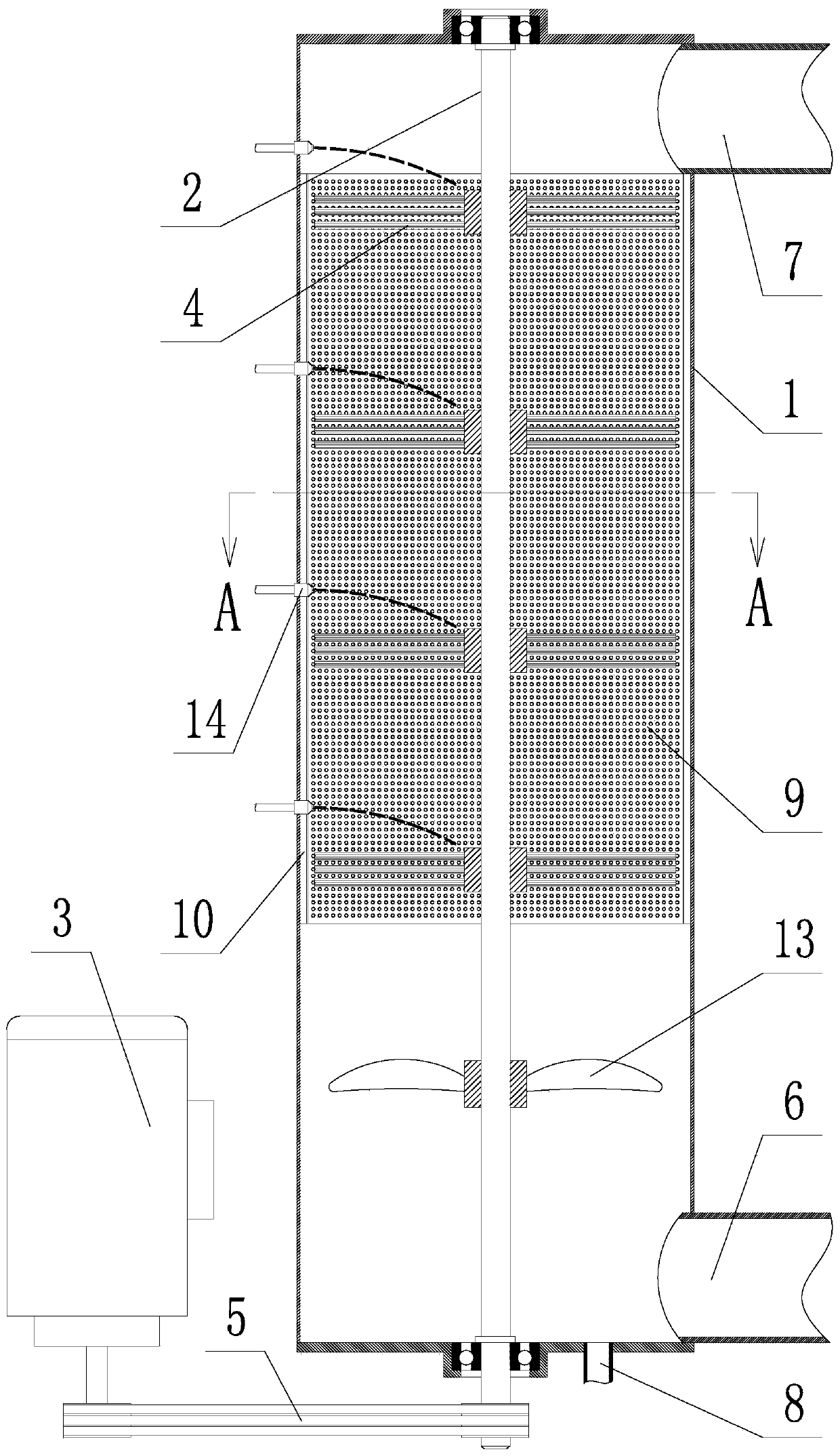
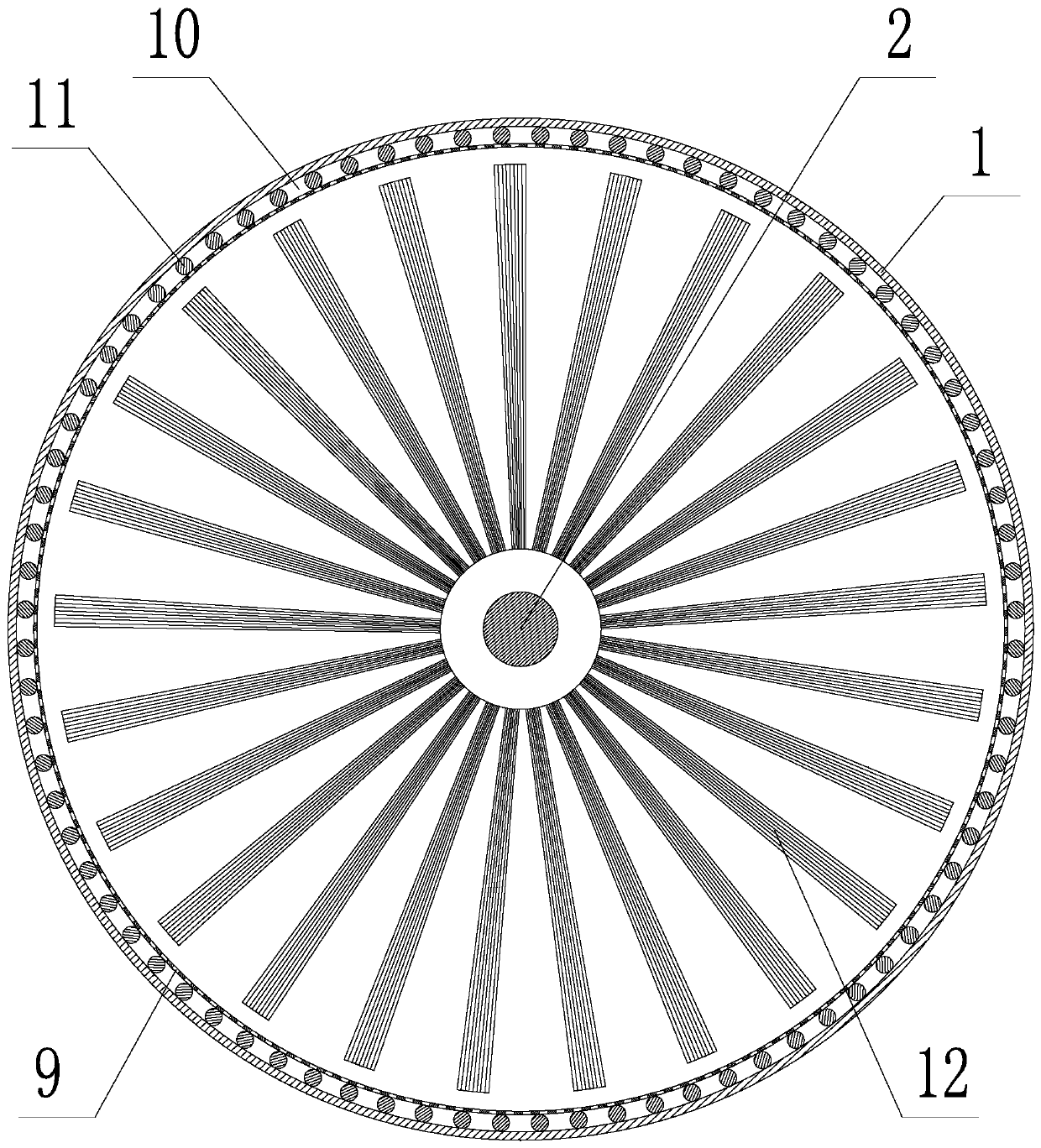
[0052] In this embodiment, the cylinder body 1 of the device has a diameter of 600mm, and the flue gas throughput is 6000m 3 / h, the brush 4 adopts a disk-type installation structure on the rotating shaft 2, and the number of brush disks 12 is four.

[0053] An active final purification method of industrial flue gas, which is used for demisting and saline-alkali soluble substances, the steps are:

[0054] ①. Establish a flue gas passage pipe (that is, the cylinder 1 in the device), set up a flue gas inlet in the lower part of the pipe (that is, the flue gas inlet 6 in the device), and set up a flue gas outlet in the upper part of the pipe (that is, the flue gas in the device export7);

[0055] ②. A shaft with a brush and capable of high-speed rotation is set up inside the pipeline (that is, the brush 4 and the rotating shaft 2 in the device, and the high-speed rotation of the rotating shaft 2 is realized by driving the motor 3 and the belt and pulley mechanism 5 );

[0056]...

Embodiment 2

[0061] In this embodiment, the cylinder body 1 of the device has a diameter of 800mm, and the flue gas throughput is 8000m 3 / h, the brush 4 adopts a disk-type installation structure on the rotating shaft 2, and the number of brush disks 12 is four.

[0062] An active industrial flue gas terminal purification method for secondary desulfurization, the steps are:

[0063] ①. Establish a flue gas passage pipe (that is, the cylinder 1 in the device), set up a flue gas inlet in the lower part of the pipe (that is, the flue gas inlet 6 in the device), and set up a flue gas outlet in the upper part of the pipe (that is, the flue gas in the device export7);

[0064] ②. A shaft with a brush and capable of high-speed rotation is set up inside the pipeline (that is, the brush 4 and the rotating shaft 2 in the device, and the high-speed rotation of the rotating shaft 2 is realized by driving the motor 3 and the belt and pulley mechanism 5 );

[0065] ③, the flue gas is passed into the ...

Embodiment 3

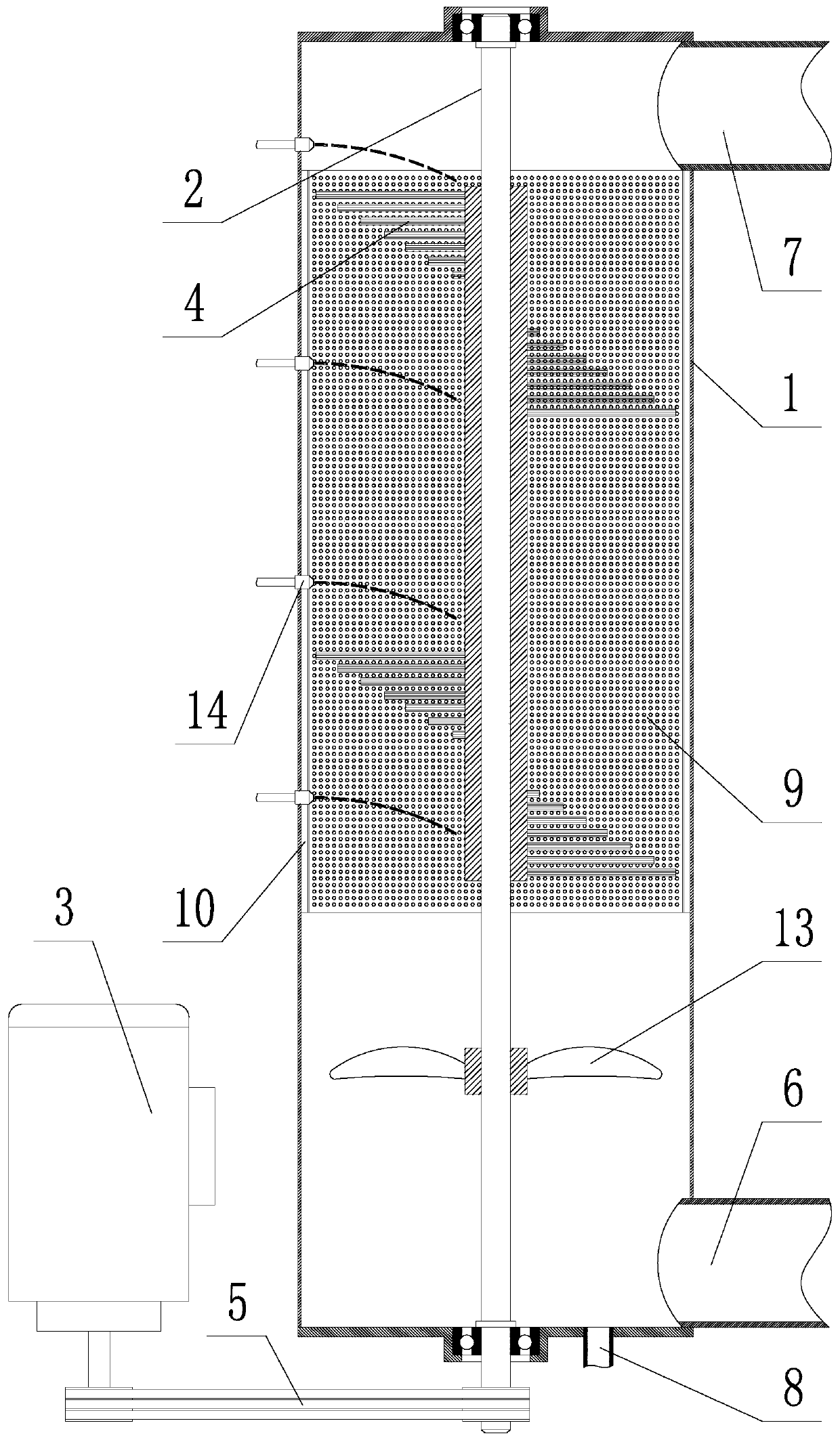
[0069] In this embodiment, the cylinder body 1 of the device has a diameter of 1000mm, the flue gas throughput is 10000m3 / h, and the brush 4 adopts a spiral installation structure on the rotating shaft 2 .

[0070] An active final purification method of industrial flue gas, which is characterized in that it is used for secondary denitrification, and the steps are:

[0071] ①. Establish a flue gas passage pipe (that is, the cylinder 1 in the device), set up a flue gas inlet in the lower part of the pipe (that is, the flue gas inlet 6 in the device), and set up a flue gas outlet in the upper part of the pipe (that is, the flue gas in the device export7);

[0072] ②. A shaft with a brush and capable of high-speed rotation is set up inside the pipeline (that is, the brush 4 and the rotating shaft 2 in the device, and the high-speed rotation of the rotating shaft 2 is realized by driving the motor 3 and the belt and pulley mechanism 5 );

[0073] ③, the flue gas is passed into th...


PUM

PropertyMeasurementUnit
diameteraaaaaaaaaa
diameteraaaaaaaaaa

Abstract

The invention relates to an active industrial smoke gas tail stage purification method, which comprises the steps that a smoke gas passing pipeline is built; a smoke gas inlet is formed in the lower part of the pipeline; the upper part of the pipeline is provided with a smoke gas outlet; a shaft which is provided with a hairbrush and can rotate at high speed is arranged inside the pipeline; the smoke gas is introduced into the pipeline from the smoke gas inlet; the introduced smoke gas is subjected to homogenization treatment, so that the smoke gas is prevented from generating segregation; the shaft with the hairbrush rotates at high speed; the hairbrush rotating at high speed is used for capturing fogdrop in the smoke gas; under the centrifugal effect, the fogdrop on the hairbrush can be continuously thrown to the inner wall of the pipeline; the flow is downwards guided through the inner wall of the pipeline until the fogdrop flow out through a liquid discharging opening formed in the bottom end of the pipeline; flowing-out liquid is directly discharged into a desulfurizing liquid pool or a denitration liquid pool to be continuatively used; the fog and saline and alkaline type soluble substance removal is completed; meanwhile, during secondary dust removal, only clean water needs to be sprayed on the hairbrush; during secondary desulfurization, only alkali liquid needs to be sprayed on the hairbrush; during secondary denitration, only a liquid phase complexation denitration agent needs to be sprayed on the hairbrush.

Description

technical field [0001] The invention belongs to the technical field of industrial flue gas purification, and in particular relates to an active final purification method of industrial flue gas. Background technique [0002] At present, under the industrial flue gas emission standards, the flue gas discharged from industrial boilers must go through denitrification, desulfurization and dust removal processes to reduce the concentration of nitrogen oxides, sulfur dioxide, and soot to below the standard value, and then industrial flue gas is allowed. released into the atmosphere. [0003] However, the industrial flue gas after denitrification, desulfurization and dust removal still has high humidity, and the industrial flue gas at this stage is mainly discharged into the atmosphere in the form of mist droplets, and in the mist droplets of industrial flue gas , will dissolve a large amount of solute substances such as sulfate, nitrate and desulfurization and denitrification agen...

Claims


Application Information

Patent Timeline
Patent Type & Authority Patents(China)
IPC IPC(8): B01D50/00B01D45/14B01D53/78B01D53/50B01D53/56B01D53/75
CPCB01D45/14B01D50/00B01D53/507B01D53/56B01D53/75B01D53/78B01D2258/0283
Inventor 符朝伟孙中强邵桂林
Owner 符朝伟
Learn More