Machining device with waste scrap extrusion function
A technology of processing equipment and functions, applied in metal processing equipment, metal processing, metal processing mechanical parts, etc., can solve the problems that processing equipment cannot realize automatic loading and unloading, processing waste is difficult to collect, and adding extrusion power, etc. The effect of automatic clamping, simple adsorption and collection problems, and simplified equipment
- Summary
- Abstract
- Description
- Claims
- Application Information
AI Technical Summary
Problems solved by technology
Method used
Image
Examples
Embodiment 1
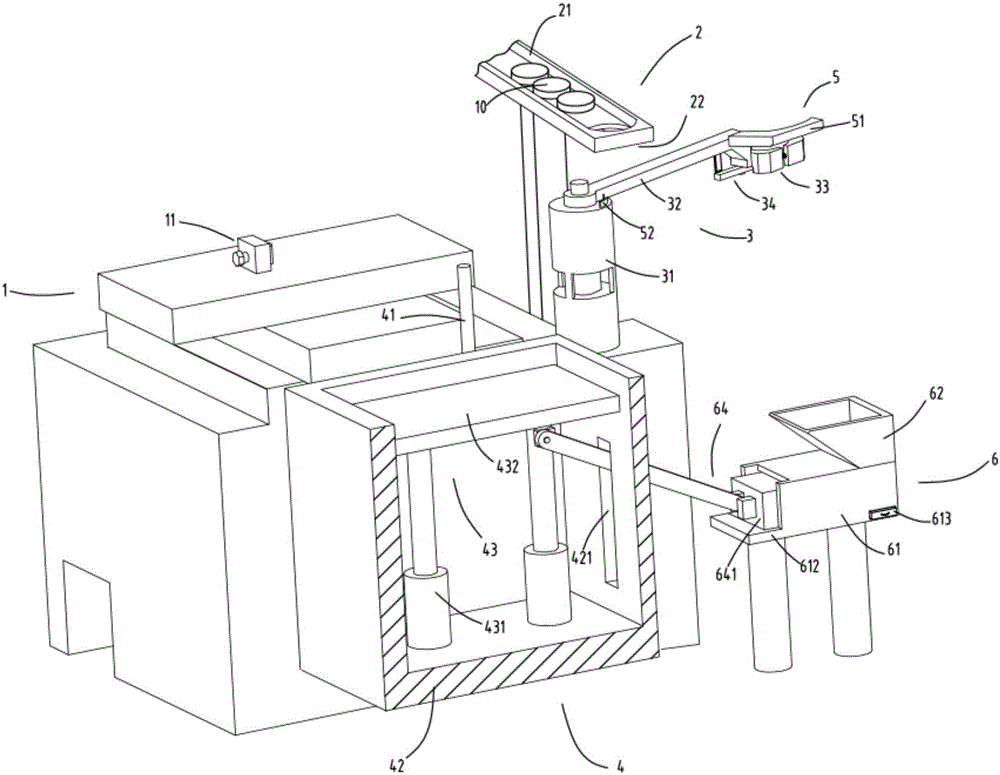
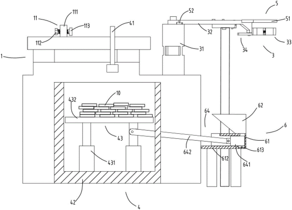
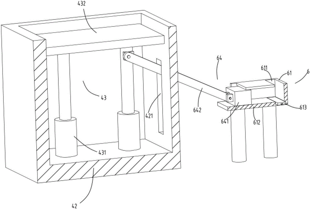
[0039] figure 1 is a schematic diagram of processing equipment with waste extrusion function, figure 2 Schematic diagram of the front view when compressing waste for processing equipment with waste squeezing function, image 3 It is a schematic diagram of the structure of the blanking part and the waste compression collection device, Figure 4 It is a partial structural schematic diagram of the feeding device, Figure 5 It is a schematic diagram of the structure of the feeding part, Figure 6 It is a schematic diagram of the structure of the electromagnetic adsorption head. Such as figure 1 , figure 2 , image 3 , Figure 4 , Figure 5 and Figure 6 As shown, what is provided in this embodiment is a processing equipment with a waste chip extrusion function, including a feeding part 2, a conveying track 21 and a blanking part 22 arranged at the end of the conveying track 21; a feeding device 3, It is used to accept the workpiece 10 falling from the blanking part 22 ...
Embodiment 2
[0056] Such as figure 1 , figure 2 , image 3 , Figure 4 , Figure 5 with Figure 6 As shown, the components that are the same as or corresponding to those in the first embodiment are marked with the corresponding reference numerals in the first embodiment. For the sake of simplicity, only the differences from the first embodiment will be described below. The difference between the second embodiment and the first embodiment is that a guide rod 334 is also provided between the fixed clamp block 331 and the movable clamp block 332, one end of the guide rod 334 is fixed on the fixed clamp block 331, and the other end is relatively movable. The guide groove 3321 provided on the clamp block 332 slides; the elastic member 333 is sheathed on the guide rod 334, and the guide rod 334 can guide the movement of the movable clamp block 332 to prevent it from being squeezed and shifted.
[0057] Workflow: The feeding device 3 feeds at the position of the feeding part 2, and the clam...
PUM
 Abstract
Description
Claims
Application Information
 - R&D
- Intellectual Property
- Life Sciences
- Materials
- Tech Scout
- Unparalleled Data Quality
- Higher Quality Content
- 60% Fewer Hallucinations
Browse by: Latest US Patents, China's latest patents, Technical Efficacy Thesaurus, Application Domain, Technology Topic, Popular Technical Reports.
© 2025 PatSnap. All rights reserved.Legal|Privacy policy|Modern Slavery Act Transparency Statement|Sitemap|About US| Contact US: help@patsnap.com


