Supercharge Your Innovation With Domain-Expert AI Agents!

Oil product filter device

A filter device and oil product technology, which is applied in the petroleum industry, processing hydrocarbon oil, and only multi-stage serial refining process treatment, etc., can solve the problems of affecting engine combustion performance, engine fuel injection nozzle blockage, engine work abnormality, etc. , to achieve the effect of simple structure, increased filtration capacity, economical and practical

Inactive Publication Date: 2017-06-06
山东重能动力有限公司
View PDF5 Cites 0 Cited by
  • Summary
  • Abstract
  • Description
  • Claims
  • Application Information

AI Technical Summary

Problems solved by technology

Moisture affects the combustion performance of the engine. Too much metal debris can easily cause the engine fuel injector to be blocked, resulting in abnormal engine performance and unstable engine power.

Method used


Image

  • Oil product filter device
  • Oil product filter device
  • Oil product filter device

Examples


Embodiment 1

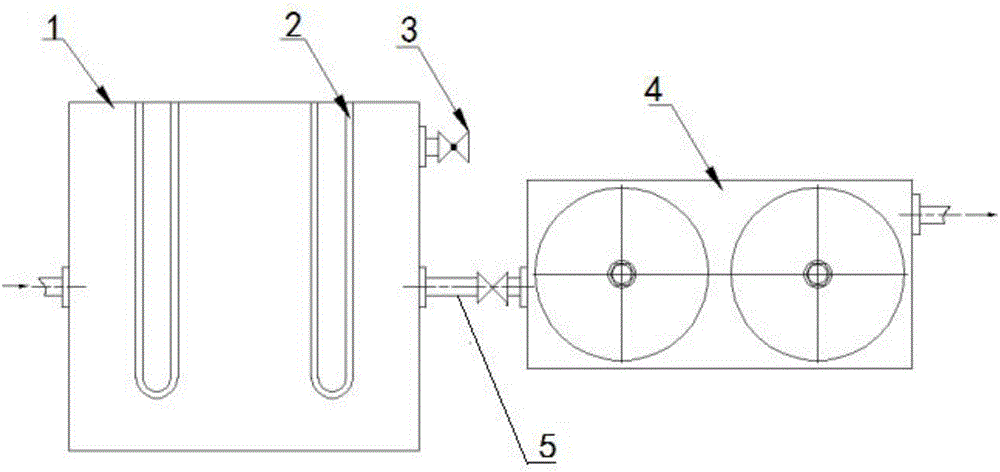
[0030] Such as figure 1 , 3 , 4, the present embodiment provides an oil filtering device, including a heating oil tank 1 and a filter 4, a heating device is arranged in the heating oil tank 1, an oil inlet port is provided on the side wall of the heating oil tank 1, and the heating oil tank 1 The upper part is provided with an air release valve 3; the heating oil tank 1 communicates with the oil inlet 15 of the filter 4 through the oil inlet pipeline 5, and the filter 4 includes an outer cover 11, a filter element 13 and a base 9, and the outer cover 11 is fixedly arranged on the base 9, The filter element 13 is placed in the outer cover 11 , and a magnet 14 is arranged in the filter element 13 , and the oil product is used for filtering by the filter element 13 and then discharged through the oil outlet 18 .

[0031] The heating device in the oil filter device is a heating tube 2, and there are multiple sets of heating tubes 2, which can quickly and fully heat the tire pyrol...

Embodiment 2

[0037] Such as figure 2 As shown, this embodiment provides an oil filter device, the structure of which is basically the same as that of Embodiment 1, except that:

[0038]In this embodiment, the oil filter device is provided with two sets of filters 4, each set includes two filters 4 arranged in series, and each filter set passes through the first communication pipeline 7, the second communication pipeline 8 and the oil inlet pipeline respectively. 5 are connected, and the first communication pipeline 7 and the second communication pipeline 8 are provided with on-off valves, and the oil inlet pipeline 5 is provided with a main valve 6 .

[0039] That is to say, the mode of one standby and one use is set in this embodiment. During the process of filtering work, two groups of filters are carried out by adjusting the opening and closing states of the switch valves on the first communication pipeline 7 and the second communication pipeline 8. Switching use of the filter 4; open...


PUM


Abstract

The invention discloses an oil product filter device which comprises a heating oil tank and filters, wherein a heating device is arranged in the heating oil tank; an oil inlet opening is formed in a side wall of the heating oil tank; a vent valve is arranged at the upper part of the heating oil tank; the heating oil tank is communicated with oil inlets of the filters via an oil inlet pipeline; the filters comprise housings, filter elements and bases; the housings are fixedly arranged on the bases; the filter elements are placed in the housings; magnets are arranged in the filter elements; an oil product is discharged from oil outlets after filtration by the filter element. The oil product filter device is simple in structure, economical, practical, and convenient to maintain; after entering the heating oil tank through a pipeline from an oil storage tank, the oil product is heated and can generate flocky impurities; the impurities is filtered out by the filter element; in addition, the oil product filter device employs a double filter structure and is provided with the two filters to increase filter capacity; the oil product filter device further employs a one-operating and one-standby mode; one filter operates; the other one is standby; the cleaning of the filters can be achieved in a starting-up state.

Description

technical field [0001] The invention relates to the technical field of filtering devices, in particular to an oil filtering device. Background technique [0002] The viscosity of tire pyrolysis oil is much lower than that of heavy diesel oil and marine fuel oil, and its calorific value is also equivalent to that of heavy diesel oil. The speed of diesel engine is low. The air is mixed and vaporized, resulting in more complete combustion. Therefore, it is entirely feasible to use tire pyrolysis oil as fuel. In the prior art, tire pyrolysis oil is subjected to multiple distillations, and then the tire pyrolysis oil and diesel oil are mixed in different proportions and then burned. Generally, the ratio is 7 to 9:1. The engine can run normally, and all tire pyrolysis oil is used. Combustion occurs and the engine cannot run normally. According to the above method, the cost of tire pyrolysis oil is basically the same as that of diesel oil, and the cost will not fall but rise aft...

Claims


Application Information

Patent Timeline
IPC IPC(8): C10G53/02B03C1/30
CPCC10G53/02B03C1/30C10G2300/1037
Inventor 刘东伟
Owner 山东重能动力有限公司
Features
  • R&D
  • Intellectual Property
  • Life Sciences
  • Materials
  • Tech Scout
  • Unparalleled Data Quality
  • Higher Quality Content
  • 60% Fewer Hallucinations
Learn More