Eureka AIR delivers breakthrough ideas for toughest innovation challenges, trusted by R&D personnel around the world.

Energy-saving fresh air treatment equipment

A technology for fresh air treatment and equipment, applied in mechanical equipment, lighting and heating equipment, ventilation systems, etc., can solve the problem of waste of condensed water resources, and achieve the effect of solving the problem of condensing water treatment and saving water sources.

Active Publication Date: 2017-06-06
福州鹏飞制冷设备有限公司
View PDF7 Cites 5 Cited by
  • Summary
  • Abstract
  • Description
  • Claims
  • Application Information

AI Technical Summary

Problems solved by technology

[0004] The technical problem to be solved by the present invention is: to provide an energy-saving fresh air treatment equipment, by adding a water storage tank at the bottom of the evaporation section, according to the water level of the storage tank Transport the condensed water in the reservoir to the external unit to provide water for the high-pressure coil in the external unit after being compressed by the compressor, and solve the problem of waste of condensed water resources in the existing air treatment equipment

Method used


Image

  • Energy-saving fresh air treatment equipment
  • Energy-saving fresh air treatment equipment
  • Energy-saving fresh air treatment equipment

Examples


Embodiment 1

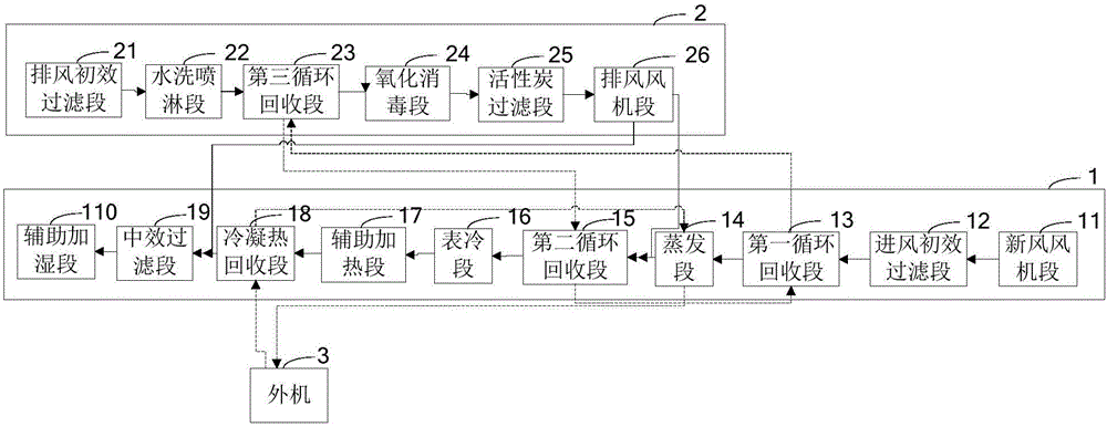
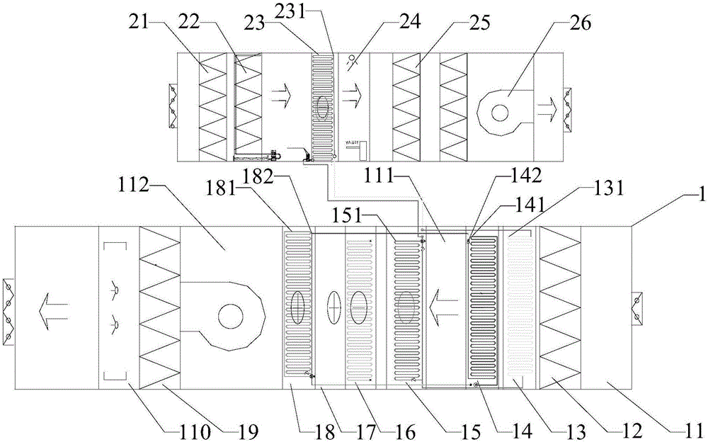
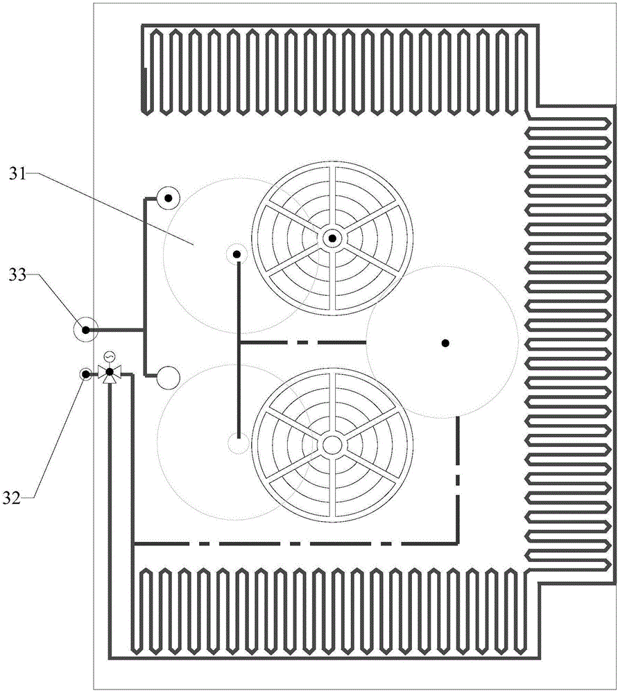
[0048] Please refer to Figure 1 to Figure 3 , an energy-saving fresh air device, including an external unit 3, an air inlet unit 1 and an exhaust fan unit 2;

[0049] The air intake unit 1 has the following structures and functions:

[0050] The air inlet unit 1 is arranged in sequence from the fresh air inlet end to the fresh air outlet end with a fresh air fan section 11, an inlet air primary filter section 12, a first circulation recovery section 13, an evaporation section 14, a second circulation recovery section 15, and a surface cooling section. Section 16, auxiliary heating section 17, condensation heat recovery section 18, mid-efficiency air inlet filter section 19 and auxiliary humidification section 110;

[0051] The fresh air fan section 11 is used to draw external fresh air into the air intake unit 1;

[0052] The primary air inlet filter section 12 is used for preliminary filtering of fresh air;

[0053] The surface cooling section 16 is connected to the centr...

Embodiment 2

[0091] On the basis of Embodiment 1, a reservoir is set at the bottom of the evaporation section 14, and an electric three-way valve for the spray section is set at the water inlet end of the washing spray section 22, and the electric three-way valve for the spray section is connected to the central controller. The first inlet end of the electric three-way valve of the spray section is connected to a tap water source, the second inlet end of the electric three-way valve of the spray section is connected to the reservoir at the bottom of the evaporation section 14 through a pipeline, and the electric three-way valve of the spray section The outlet end of the valve is connected to a spray pipe, the spray pipe is provided with a water washing spray pump, the reservoir is provided with a liquid level sensor, and the liquid level sensor includes a high water level sensor and a low water level sensor, so The liquid level sensor is connected to the central controller, and the bottom o...

Embodiment 3

[0094] According to a kind of energy-saving fresh air device described in Embodiment 1, a primary air return port 111 is added after the evaporation section 14, and a secondary air return port 112 is added after the condensation heat recovery section 18; The secondary air return system, the secondary air return system includes a return air duct connected behind the exhaust fan section 26, and the return air duct includes a return air main pipe, a primary exhaust duct branched by the return air main pipe and a secondary air return pipe , the primary air return pipe is connected to the primary air return port 111, and the secondary air return pipe is connected to the secondary air return port 112; the primary return air pipe, the secondary air return pipe and the return air main pipe are provided with a diverter valve at the diversion point, the said The air flow split by the primary return air duct is 30% of the air flow of the main return air duct, and the air flow divided by t...


PUM


Abstract

The invention relates to energy-saving fresh air treatment equipment which comprises an air feeding unit, an air discharging unit and an outdoor unit, wherein the air feeding unit consists of a fresh air fan section, an evaporation section, an air feeding primary filter section, a surface cooling section, an auxiliary heating section, a condensation heat recycling section, an air feeding moderate filter section and an auxiliary humidification section which are arrayed in sequence from the fresh air inlet end to the fresh air outlet end; the air discharging unit comprises a washing spraying section; an impounding reservoir is arranged at the bottom of the evaporation section; an outdoor unit electric three-way valve is arranged at the water feeding end of a cooling spraying pipe; the outdoor unit electric three-way valve is connected with a central controller; the first inlet end of the outdoor unit electric three-way valve is connected with a tap water source; the second inlet end of the outdoor unit electric three-way valve is connected with the impounding reservoir at the bottom of the evaporation section through a pipeline; the outlet end of the outdoor unit electric three-way valve is connected with a cooling spraying pipe. Therefore, a water source is supplied for cooling of the outdoor unit, and condensation water sources can be fully utilized.

Description

technical field [0001] The invention relates to the field of air treatment, in particular to energy-saving fresh air treatment equipment. Background technique [0002] The air conditioning system aims to provide a controllable, comfortable and healthy air environment for people's indoor activity space or provide specific air environment conditions for storage, processing, equipment operation and other activities. The main controls of air conditioning include air quality, air temperature, air humidity, and wind speed. [0003] The more natural and effective way to control air quality is to use outdoor fresh air to replace or dilute the indoor air, that is, to inhale outdoor fresh air and discharge indoor exhaust air, and to dehumidify outdoor high-humidity fresh air. Condensation dehumidification is generally used, and the moisture in the air will Condensate on the condensing coil to obtain condensed water, and the existing air treatment equipment generally drains the above-...

Claims


Application Information

Patent Timeline
Patent Type & Authority Applications(China)
IPC IPC(8): F24F3/14F24F3/16F24F12/00F24F13/28F24F13/30F24F1/42F24F13/22
CPCF24F1/42F24F3/14F24F3/16F24F12/00F24F13/22F24F13/28F24F13/30F24F8/117F24F8/108F24F8/158F24F8/20Y02B30/56
Inventor 林礼建温承坤
Owner 福州鹏飞制冷设备有限公司
Why Eureka
Eureka Blog
Learn More