Four-shaft combined precise drive steering engine device

A steering gear, precision technology, applied in the direction of projectiles, self-propelled bombs, offensive equipment, etc., can solve problems such as complex structure, high maintenance cost, impact of return clearance, etc., to improve the control range, facilitate disassembly and maintenance, and increase control effect of ability

Inactive Publication Date: 2017-06-09
CHINA ACAD OF AEROSPACE AERODYNAMICS
View PDF7 Cites 9 Cited by
  • Summary
  • Abstract
  • Description
  • Claims
  • Application Information

AI Technical Summary

Problems solved by technology

[0003] As the demand for portable missiles or arrows in modern warfare becomes more and more urgent, the performance requirements of portable missiles or arrows are also continuously strengthened. The higher the deflection accuracy of the wing is, the more complex the attitude is, the more the deflection angle of the rudder or the wing is required; in addition, the portable missile or rocket launcher needs to cope with various complex temperature environments without affecting its performance. Structural design and layout of machine installations pose great challenges
However, traditional steering gears such as hydraulic and pneumatic steering gears have complex structures, large volumes, and high maintenance costs, and are not suitable for portable missiles. In addition, the screw-nut drive, in order to prevent the rudder deflection angle error caused by the rotation of the nut, It needs to be used with miniature linear guide rails, and the friction gap between the nut and the shift fork also needs to be constantly adjusted, which has a great impact on the return gap of the entire device. The most important thing is that the screw-nut transmission can provide the rudder deflection angle of the rudder shaft The angle range cannot be too large, which limits the control range of the portable missile to the flight attitude

Method used


Image

  • Four-shaft combined precise drive steering engine device

Examples


Embodiment Construction

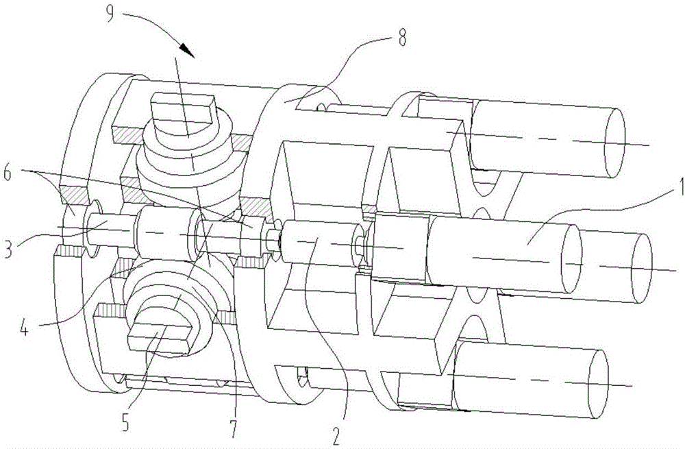
[0021] According to the attached figure 1 Specific embodiments of the present invention are further described in detail.

[0022] It includes a motor drive system (1), a rudder shaft drive unit (3-5) and a steering gear main structure (8);

[0023] The main structure of the steering gear (8) is used to connect the steering gear device inside the main body of the portable missile; the main structure of the steering gear (8) is a three-layer structure, and the top layer is respectively provided with four flange holes along the circumference for fixing four sets of Motor drive system (1); the first bearing hole is set at the position corresponding to the flange hole in the middle layer, and the first bearing is set inside, the upper end of the worm 3 passes through the first bearing bearing to connect to the coupling 2, and the coupling 2 is connected to the motor drive system ( 1) at the output end, the bearing is arranged in the bearing hole, and the bearing hole is used to li...


PUM


Abstract

The invention relates to a four-shaft combined precise drive steering engine device which comprises motor driving systems, rudder shaft driving units and a steering engine main body structure, wherein the steering engine main body structure is used for connecting the steering engine device to the interior of a portable guided missile main body; totally four sets of motor driving systems are uniformly distributed along the peripheral direction; the output end of each set of motor driving system is connected with a worm; totally four sets of rudder shaft driving units are arranged, and each set comprises a worm, a worm gear and a rudder shaft; the worms drive the worm gears to rotate under the drive of the motor driving systems; and the worm gears drive the rudder shafts to rotate by virtue of bearings arranged therein. The steering engine main body is integrally processed, the device structure is simple, each component is convenient to dismount and maintain, the whole device has the outer diameter of less than 60mm, can be fixedly connected with the portable guided missile or rocket gun main body, has the inner diameter of more than 15mm and can be used for wiring of various communication lines. Meanwhile, the total weight of the whole device is less than 1kg, and the weight proportion of the device is reduced in the weight of the portable guided missile.

Description

technical field [0001] The invention relates to a four-axis combination precision-driven steering gear device, which belongs to the field of electric steering gear structure design. Background technique [0002] As the control device of precision guided weapons, the electric steering gear receives the rudder deflection angle command issued by the onboard computer or autopilot, overcomes the hinge moment of the rudder surface and performs fast angular position tracking, thereby changing the flight attitude and flight trajectory of the guided weapon. To achieve the expected launch effect. For portable missiles or arrow guns, the narrow internal space poses a challenge to the structural design of the electric steering gear, especially for the precise drive control of the four canards or tail fins. Designing an electric steering gear in a portable missile or arrow launcher needs to consider many factors, such as the size and weight of the steering gear, the rudder deflection an...

Claims


Application Information

Patent Timeline
Patent Type & Authority Applications(China)
IPC IPC(8): F42B15/01
CPCF42B15/01
Inventor 李广良杨辉董金刚魏忠武
Owner CHINA ACAD OF AEROSPACE AERODYNAMICS
Why Eureka
Try Eureka