
A voltage compensation method and circuit for eliminating the influence of dvr on adjacent loads

A voltage compensation and load technology is applied in the field of voltage compensation methods and circuits to eliminate the influence of DVR on adjacent loads, and can solve problems such as the influence of adjacent loads.

Active Publication Date: 2019-12-10
SOUTH CHINA UNIV OF TECH +1
View PDF2 Cites 0 Cited by
  • Summary
  • Abstract
  • Description
  • Claims
  • Application Information

AI Technical Summary

Problems solved by technology

There are currently three basic voltage drop compensation strategies commonly used: voltage compensation before drop, in-phase voltage compensation, and minimum energy compensation. The change of the adjacent load voltage, therefore, the access of the dynamic voltage restorer (DVR) will inevitably have a certain impact on the adjacent load

Method used

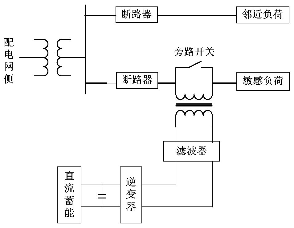
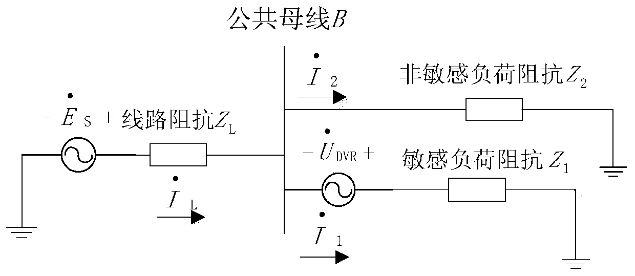
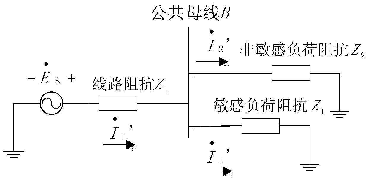

Image

  • A voltage compensation method and circuit for eliminating the influence of dvr on adjacent loads
  • A voltage compensation method and circuit for eliminating the influence of dvr on adjacent loads
  • A voltage compensation method and circuit for eliminating the influence of dvr on adjacent loads

Examples


Embodiment 1

[0090] A voltage compensation method for eliminating the impact of DVR on adjacent loads, comprising the following steps:

[0091] Step 1: beta set calculate

[0092] For simplicity, determine β set The principle of size is consistent with the previous assumption. The equivalent impedance of the sensitive load and the non-sensitive load are the same, so the normal current of the sensitive load and the normal current of the adjacent non-sensitive load are equal in size and phase, and the normal current of the two can be set The amplitudes of both are 1; after the system voltage drops, the current amplitudes of both decrease to x 1 , the phase angle change value is β, and the phase shift makes β=β set ,Satisfy The end point of falls exactly on an event current circle, such as Figure 7 As shown, at this time The amplitude is x 2 , then in with The phasor triangle of satisfies the law of cosines:

[0093]

[0094] remember exist with In the phasor triangle ...

Embodiment 2

[0117] As a voltage compensation device that provides a stable and reasonable voltage working environment for sensitive loads, DVR is generally used in medium and low voltage distribution networks, and medium and low voltage distribution networks are mostly three-phase four-wire systems. system, this technical solution uses three single-phase full-bridge structures as the simulation model. The energy storage device chooses a supercapacitor. Since it is a low-voltage distribution network, the voltage level is not high. The coupling type is relatively simple capacitive coupling, and the filter is composed of reactance and coupling capacitance.

[0118] Assuming that the three-phase output voltages are independent of each other and do not interfere with each other, it is possible to simulate a single-phase DVR compensation circuit and analyze and study its corresponding compensation effect. Set up a distribution network terminal system, which consists of a single-phase power supp...


PUM


Abstract

The invention provides a voltage compensation method and circuit that eliminate the influence of DVR on adjacent load. The method comprises the following steps: when a system voltage suffers a temporary drop, the current amplitudes of a sensitive load and the adjacent non-sensitive load are reduced as X1, the phase angle change value is represented as beta and through phase shifting, beta is equal to beta[set], and the finish point that meets I2'' happens to drop on the current circle of the primary event. The phase angle of U1 subtracted by beta[set] is combined with the amplitude value of U1 to form the target voltage vector U1''. Through the subtraction of the target voltage vector U1'' from the standard voltage vector, deltaU1 is obtained. Through a hysteresis comparator, a PWM driving signal is obtained. The PWM driving signal drives an inversion unit. The signal outputted from the inversion unit generates ideal compensation voltage through the filtering unit. According to the voltage compensation method and the circuit, it is possible to eliminate the influence of DVR on the adjacent load effectively.

Description

technical field [0001] The invention relates to the field of grid power supply, in particular to a voltage compensation method and circuit for eliminating the influence of a DVR on adjacent loads. Background technique [0002] Dynamic voltage restorer (DVR) is a new type of series voltage compensation device connected in series between the system power grid and sensitive user loads, which can effectively eliminate voltage fluctuations, voltage flicker, asymmetry of each phase voltage and short-term power supply interruption It has the advantages of good dynamic performance, low economic cost and good compensation benefits. [0003] A dynamic voltage restorer (DVR) can be equivalent to a controlled voltage source, which has the function of energy output. In the working state, it can input energy to the grid system. Its installation configuration in the power system is as follows: figure 1 shown. [0004] The working principle of dynamic voltage restorer (DVR): [0005] Suc...

Claims


Application Information

Patent Timeline
Patent Type & Authority Patents(China)
IPC IPC(8): H02J3/12
CPCH02J3/12
Inventor 杜兆斌戴观权管霖刘嘉林周保荣洪潮
Owner SOUTH CHINA UNIV OF TECH
Learn More