
Energy-saving, high-gradient and high-intensity magnetic separator

A high-gradient, strong magnetic separation technology, applied in the direction of magnetic separation, solid separation, chemical instruments and methods, etc., can solve the problems of high energy consumption of equipment, high manufacturing cost, high energy consumption, etc., to reduce the cost of mineral processing, mechanical Easy to equip and increase throughput

Inactive Publication Date: 2017-06-13
攀枝花市焱乾富慧科技有限公司
View PDF7 Cites 6 Cited by
  • Summary
  • Abstract
  • Description
  • Claims
  • Application Information

AI Technical Summary

Problems solved by technology

[0003] In the sorting of weakly magnetic minerals such as ilmenite and hematite, the most used is the vertical ring pulsating high-gradient magnetic separator whose publication number is CN86106144A. This magnetic separator is used as a tailing equipment for weakly magnetic minerals. It has many advantages of high processing efficiency, large processing capacity, and the medium is not easy to be blocked, but the strong magnetic machine has many disadvantages: its operating cost is high, the equipment is expensive, and many private enterprises or small-scale factories and mines cannot even afford this equipment
[0004] It can be seen that the traditional strong magnetic separator has defects such as large energy consumption, large equipment volume, high energy consumption, large copper consumption, and high manufacturing cost, and needs to be further improved.

Method used


Image

  • Energy-saving, high-gradient and high-intensity magnetic separator
  • Energy-saving, high-gradient and high-intensity magnetic separator
  • Energy-saving, high-gradient and high-intensity magnetic separator

Examples


Embodiment Construction

[0032] The following examples are used to illustrate the present invention, but are not intended to limit the scope of the present invention.

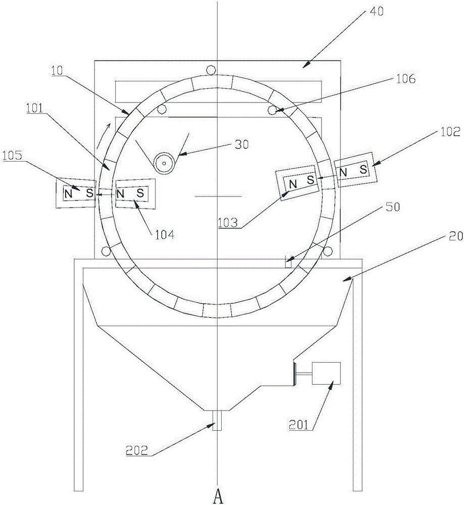
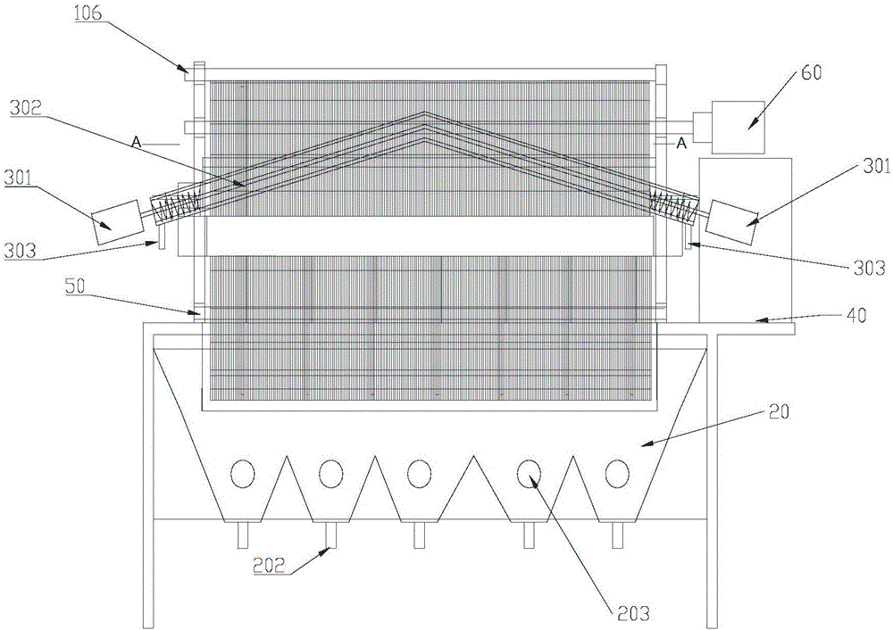
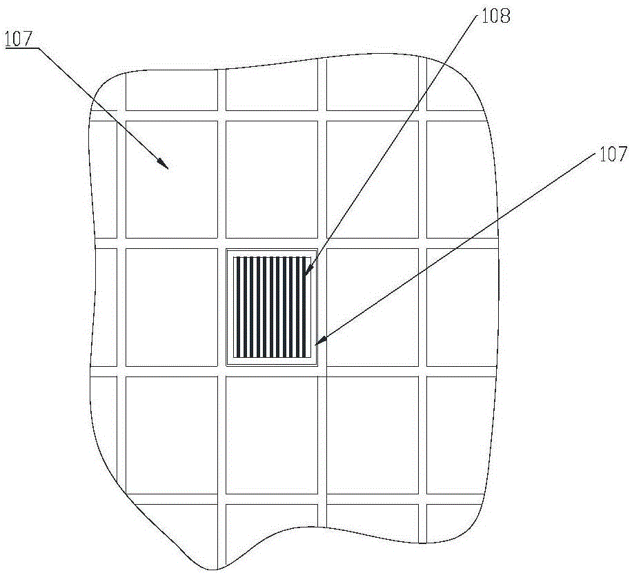
[0033] Such as Figure 1 to Figure 3 As shown, the energy-saving high-gradient strong magnetic separator of the present invention comprises a magnetic separation device 10, a feeding device 30, a feeding device 50 and a sorting box 20, wherein the magnetic separation device 10 comprises a magnetic separation drum 101, a magnetization The driving device 60 of the magnetic system, the demagnetization magnetic system and the magnetic separation drum, the magnetic separation drum 101 is provided with a medium rod 108 along the circumferential direction of the magnetic separation drum 101; the feeding device 50 is located on the magnetic separation drum The lower end of the inner space of 101 is conducive to the position where the medium rod on the magnetic separation drum fully absorbs the weakly magnetic mineral particles, and facilitates...


PUM


Abstract

The invention relates to an energy-saving, high-gradient and high-intensity magnetic separator. The energy-saving, high-gradient and high-intensity magnetic separator comprises a magnetic separation device, a conveying device, a feeding device and a sorting box, wherein the magnetic separation device comprises a magnetic separation drum, a magnetizing system, a demagnetizing system and a driving device of the magnetic separation drum, and the magnetic separation drum consists of medium rod filler and a framework thereof; the feeding device is mounted at the lower end of an inner space of the magnetic separation drum and conveys to-be-separated ore granules to the inner side of the magnetic separation drum; the sorting box is located at the lower part of the magnetic separation drum, receives ore granules left by the magnetic separation drum and keeps the drum being immersed in ore pulp. The medium rod is not required to always finish adsorption of the ore granules in a magnetic field after being made from a hard magnetic material, the air gap space of the required magnetic system is substantially narrowed, the energy consumption and the cost are reduced, and the ore treatment amount is increased.

Description

technical field [0001] The invention relates to the technical field of mineral separation machinery, in particular to an energy-saving high-gradient strong magnetic separator. Background technique [0002] In the field of weak magnetic mineral separation, strong magnetic separators are usually used as tail throwing equipment. Strong magnetic separators are divided into two categories: electromagnetic and permanent magnet. The principle of magnetic separation of electromagnetic strong magnetic machines is to use in a uniform magnetic field. The cylindrical medium rod made of soft magnetic material changes the magnetic field distribution on both sides of the medium rod to form a gradient magnetic field, so that the weak magnetic minerals are adsorbed on the surface of the medium rod due to the force; the principle of the permanent magnetic separator is to use a staggered arrangement The magnetic block forms an inhomogeneous magnetic field on its surface, and the minerals are s...

Claims


Application Information

Patent Timeline
Patent Type & Authority Applications(China)
IPC IPC(8): B03C1/14
CPCB03C1/14
Inventor 祝司云肖良艳肖良维
Owner 攀枝花市焱乾富慧科技有限公司
Learn More