
Metal forge welding additional material manufacturing device and forging method

A technology of additive manufacturing and forging welding, which is applied in the field of metal forging and welding additive manufacturing devices, can solve problems such as fast solidification and cooling speed, space lag, and coarse forging structure inside metal parts, so as to improve reliability and consistency , Reduce stress and deformation, excellent mechanical properties

Active Publication Date: 2017-06-13
青岛卓思三维智造技术有限公司
View PDF11 Cites 21 Cited by
  • Summary
  • Abstract
  • Description
  • Claims
  • Application Information

AI Technical Summary

Problems solved by technology

[0003] Compared with the forged structure, the internal structure of the metal parts obtained by the above "melting-solidification" scheme is very coarse and has obvious directionality. Although some materials have better mechanical properties after forming, in general terms, It is difficult for melt-formed materials to achieve the same comprehensive performance as forged materials
In addition, welding defects such as pores, cracks, and lack of fusion may also occur during the fusion surfacing process.
Although the melting and forging method can improve the internal quality and performance, in this composite processing method, melting and forging are completed by two different processing units, and the two have a spatial distance and a time lag, making The process and equipment are highly complex; in addition, due to the small molten pool and fast solidification and cooling speed, the forging temperature cannot be effectively controlled, which affects the scope of application of materials and the effect of forging

Method used


Image

  • Metal forge welding additional material manufacturing device and forging method
  • Metal forge welding additional material manufacturing device and forging method

Examples


Embodiment Construction

[0027] In the following, the present invention will be specifically described through exemplary embodiments. It should be understood, however, that elements, structures and characteristics of one embodiment may be beneficially incorporated in other embodiments without further recitation.

[0028] In the description of the present invention, it should be noted that the orientation or positional relationship indicated by the terms "inner", "outer", "upper", "lower", "front", "rear" etc. are based on the The positional relationship is only for the convenience of describing the present invention and simplifying the description, but does not indicate or imply that the referred device or element must have a specific orientation, be constructed and operated in a specific orientation, and thus should not be construed as limiting the present invention. In addition, the terms "first", "second", and "third" are used for descriptive purposes only, and should not be construed as indicating...


PUM


Abstract

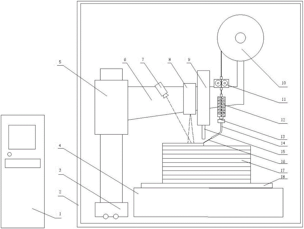
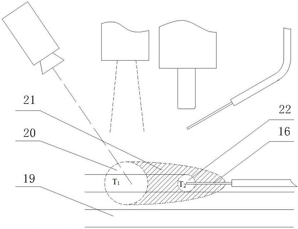
The invention provides a metal forge welding additional material manufacturing device and a forging method. The metal forge welding additional material manufacturing device comprises a work bin and a control unit connected with the work bin. The work bin is internally provided with a forging base plate, a machining unit and a moving unit. The moving unit is arranged at the side portion of the forging base plate. The machining unit is located on one side of the moving unit. The machining unit is located above the forging base plate when machining a workpiece. The machining unit comprises a preheating unit, a forging unit, a wire feeder and a wire storage device, all of which are sequentially arranged in the direction from the moving unit to the forging base plate. The forging unit comprises a forging hammer capable of reciprocating up and down, a forging area is formed between the lower portion of the forging hammer and the surface of the workpiece, the forging hammer reciprocates in the forging area, and accordingly the workpiece and a metal wire can be continuously forged. An inner microscopic structure in the manufactured material is a forging structure, grain is fine, the mechanical performance s good, air holes and other common welding metallurgical defects cannot occur, and the reliability and consistency of the metal additional material manufacturing component performance can be greatly improved.

Description

technical field [0001] The invention belongs to the field of metal additive manufacturing, and in particular relates to a metal forging and welding additive manufacturing device and a forging method. Background technique [0002] At present, the mainstream additive manufacturing method to realize the metallurgical combination of metal materials is usually "melting-solidification", which is characterized by the use of heat sources to melt and feed metal materials simultaneously, such as metal wires, powders, etc. The form realizes the manufacture of the structure, and the internal microstructure of the prepared metal material is a solidified structure. In order to improve the mechanical properties of materials and reduce internal defects, a method of combining fused deposition additives with thermomechanical processing was developed later, that is, material deposition and metallurgical integration are realized through melting, and rolling, forging or impact processes are adde...

Claims


Application Information

Patent Timeline
IPC IPC(8): B21J7/04B21J1/06B21K27/04B22F3/00B33Y40/00B22F10/10B22F12/00
CPCB21J1/06B21J7/04B21K27/04B33Y40/00B22F10/00B22F10/362B22F10/18B22F12/90B22F10/38B22F12/13B22F10/50B22F10/32Y02P10/25
Inventor 锁红波邢明
Owner 青岛卓思三维智造技术有限公司
Learn More