
Paperboard cutting machine

A slitter and cardboard technology, applied in metal processing and other directions, can solve problems such as hindering the normal rotation of the blade, affecting the normal cutting of the cardboard, damaging the cutting table, etc., to achieve the effect of facilitating normal cutting, easy removal, and keeping clean.

Active Publication Date: 2017-06-13
NINGBO JINGWEI SYSTEMTECHNIK LTD
View PDF7 Cites 8 Cited by
  • Summary
  • Abstract
  • Description
  • Claims
  • Application Information

AI Technical Summary

Problems solved by technology

But in the prior art, because the blade in the cutting mechanism rotates at a high speed, in order to prevent the blade from damaging the cutting table, or prevent the cutting table from hindering the normal rotation of the blade, the cutting table is usually not provided under the blade, so that the cardboard rolls Under the impetus of the wheel, it is suspended under the blade to cut directly
When cutting, the rotating blade will cause strong vibration of the cardboard, and the cardboard is in a suspended state at this time, which will easily cause the cardboard to slip or shift from the conveying mechanism, affecting the normal cutting of the cardboard

Method used


Image

  • Paperboard cutting machine
  • Paperboard cutting machine
  • Paperboard cutting machine

Examples


Embodiment Construction

[0021] The present invention will be described in further detail below by means of specific embodiments:

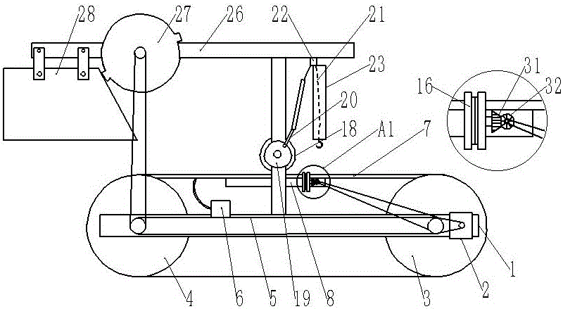
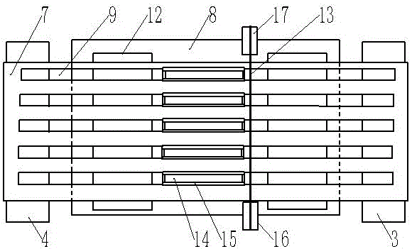
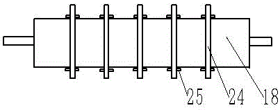
[0022] The reference signs in the drawings of the description include: frame 1, motor 2, first roller 3, second roller 4, toothed chain 5, suction fan 6, conveyor belt 7, support plate 8, through groove 9, branch pipe 10 , the first magnetic part 11, waste trough 12, elastic rope 13, cutting groove 14, block 15, driving pulley 16, driven pulley 17, cutting roller 18, disc 19, rocker 20, pull rope 21, suspension ring 22 , guide cylinder 23, blade 24, second magnetic part 25, mounting plate 26, gear 27, cardboard groove 28, opening 29, discharge port 30, first bevel gear 31, second bevel gear 32, leaking net 33.

[0023] The embodiment is basically as figure 1 and figure 2 Shown: a cardboard slitting machine, including a frame 1, the right part of the frame 1 is fixed with a motor 2, and the frame 1 is connected with a first roller 3 and a second roller 4 through bearing...


PUM


Abstract

The invention relates to the technical field of cutting equipment, and discloses a paperboard cutting machine. The paperboard cutting machine comprises a rack which is provided with a motor, a first roller and a second roller, a conveyor belt and a toothed chain are connected between the first roller and the second roller, the toothed chain is provided with a suction fan, a first belt is connected between the motor and the first roller, a through groove is formed in the conveyor belt which is internally provided with a branch pipe, the branch pipe communicates the side wall of the through groove with the suction fan and is internally provided with a first magnetic part, a support rod is arranged on the rack and provided with a support plate, a rotating shaft and a hanging ring, the support plate is provided with an elastic rope and a cutting groove, a movable block is arranged on the cutting groove, a cutting roller and a disc are arranged on the rotating shaft, a blade is arranged on the cutting roller, a second magnetic part is arranged on the blade, an eccentric column is arranged on the disc, a rocker is hinged to the eccentric column, a swing rod is hinged to the other end of the rocker, a pull hook is connected to the swing rod through a stay cord, and the stay cord penetrates through the hanging ring. Accordingly, the paperboard can be made to keep stable in the cutting process for effective cutting.

Description

technical field [0001] The invention relates to the technical field of cutting equipment, in particular to a cardboard cutting machine. Background technique [0002] Slitting machine is a kind of mechanical equipment that cuts wide cardboard, mica tape or film into multiple narrow-width materials. It is often used in papermaking machinery, wire and cable mica tape, and printing and packaging machinery. [0003] Existing cardboard slitting machines generally include a conveying mechanism and a cutting mechanism. The conveying mechanism includes rollers, and through the friction of the rollers, the cardboard is pushed to the bottom of the cutting mechanism for cutting. But in the prior art, because the blade in the cutting mechanism rotates at a high speed, in order to prevent the blade from damaging the cutting table, or prevent the cutting table from hindering the normal rotation of the blade, the cutting table is usually not provided under the blade, so that the cardboard r...

Claims


Application Information

Patent Timeline
IPC IPC(8): B26D1/15B26D7/06B26D7/01B26D7/14B26D7/18B26D5/08
CPCB26D1/15B26D5/086B26D7/018B26D7/0625B26D7/08B26D7/14B26D7/1863
Inventor 张强
Owner NINGBO JINGWEI SYSTEMTECHNIK LTD
Learn More