
Road construction sediment mixer

A technology for mixing and silting, which is applied to clay mixing devices, mixing operation control devices, clay preparation devices, etc., can solve problems such as unsatisfactory effects, increased capital consumption, and increased equipment investment, so as to reduce labor burden and reduce The probability of downtime for cleaning, the effect of improving quality

Pending Publication Date: 2017-06-13
梁正
View PDF12 Cites 5 Cited by
  • Summary
  • Abstract
  • Description
  • Claims
  • Application Information

AI Technical Summary

Problems solved by technology

[0002] In the current road construction, it is a very common step for sediment mixing, but in the process of mixing sediment, usually the filler is directly mixed with a mixer, and this method often causes mixing. The mixing is uneven, and during the mixing process, due to the large amount of sediment, the mixing time usually consumes a lot of time, so we can only passively use multiple mixers to speed up the work, which will undoubtedly increase the cost of the equipment. The investment has increased the consumption of funds, and the effect achieved is not very ideal. During the mixing process, the sediment will wear the inner wall of the mixer, resulting in a serious reduction in the life of the equipment, and the sediment will stick to the mixer when mixing. On the roller, the temperature will immediately solidify on the mixing roller. The longer the time, the thicker the solidified silt, and finally it has to be shut down for cleaning, which seriously affects the progress of the construction period, and consumes a lot of manpower, material resources and time.

Method used


Image

  • Road construction sediment mixer

Examples


Embodiment Construction

[0017] In order to facilitate the understanding of those skilled in the art, the present invention will be further described below in conjunction with the accompanying drawings.

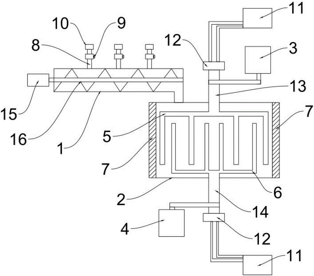
[0018] Such as figure 1 A road construction silt mixing device shown includes a mixing box 2, the side wall of the mixing box 2 is provided with a wear-resistant layer 7, and the mixing box 2 is provided with a feed pipeline 1. The feeding pipeline 1 is provided with a screw conveyor 16, and one end of the screw conveyor 16 is connected with a conveying motor 15 to drive, and the feeding pipeline 1 is provided with a number of adding pipes 8, and the adding pipes 8 are connected to the feeding pipeline 1. Add materials such as water and additives inside, so that the sediment is initially mixed in the feed pipe 1, which speeds up the mixing efficiency. The adding pipe 8 is equipped with a valve 9, and the valve 9 controls the addition of The switch of the pipe 8 avoids backflow when not in use. The a...


PUM


Abstract

The invention discloses a road construction sediment mixer, and belongs to the technical field of road engineering equipment. The road construction sediment mixer comprises a mixing tank, wherein a feeding pipeline is arranged on the mixing tank, and a spiral conveyer is arranged in the feeding pipeline; one end of the spiral conveyer is connected with a conveying motor to drive, and the top part of the mixing tank is provided with an active shaft; one end of the active shaft is provided with an active shaft, and the other end of the active shaft is in driving connection with the main motor; the bottom part of the mixing tank is provided with an assistant rotary shaft, and one end of the assistant rotary shaft is provided with an assistant roller; the other end of the assistant rotary shaft is in driving connection with an assistant motor; the rotating direction of the main motor is opposite to that of the assistant motor; the active roller and the assistant roller are arranged to be several longitudinal branches and staggered and distributed mutually; thus the road construction sediment mixer realizes the high-efficient sediment mixing, improves the mixing speed, reduces the sediment adhesion status, prolongs the service life of the equipment, and reduces the labor burden of the worker.

Description

technical field [0001] The invention relates to the technical field of road engineering equipment, in particular to a mud mixing device for road construction. Background technique [0002] In the current road construction, it is a very common step for sediment mixing, but in the process of mixing sediment, usually the filler is directly mixed with a mixer, and this method often causes mixing. The mixing is uneven, and during the mixing process, due to the large amount of sediment, the mixing time usually consumes a lot of time, so we can only passively use multiple mixers to speed up the work, which will undoubtedly increase the cost of the equipment. The investment has increased the consumption of funds, and the effect achieved is not very ideal. During the mixing process, the sediment will wear the inner wall of the mixer, resulting in a serious reduction in the life of the equipment, and the sediment will stick to the mixer when mixing. On the rollers, the temperature wi...

Claims


Application Information

Patent Timeline
Patent Type & Authority Applications(China)
IPC IPC(8): B28C3/00B28C7/10B28C7/12B28C7/04
CPCB28C3/00B28C7/04B28C7/10B28C7/12
Inventor 梁正
Owner 梁正
Learn More