Snow melting system for asphalt concrete pavement

An asphalt concrete and snow-melting technology, applied to roads, roads, pavement details, etc., can solve problems such as endangering farmland green belts, shortening road life, polluting the environment, and achieving energy shortages and environmental pollution. high heat effect

Pending Publication Date: 2017-06-13
高志斌 +1
View PDF15 Cites 12 Cited by
  • Summary
  • Abstract
  • Description
  • Claims
  • Application Information

AI Technical Summary

Problems solved by technology

However, the extensive use of deicing agents has the problems of endangerin

Method used


Image

  • Snow melting system for asphalt concrete pavement
  • Snow melting system for asphalt concrete pavement
  • Snow melting system for asphalt concrete pavement

Examples


Embodiment 1

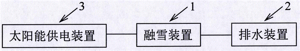
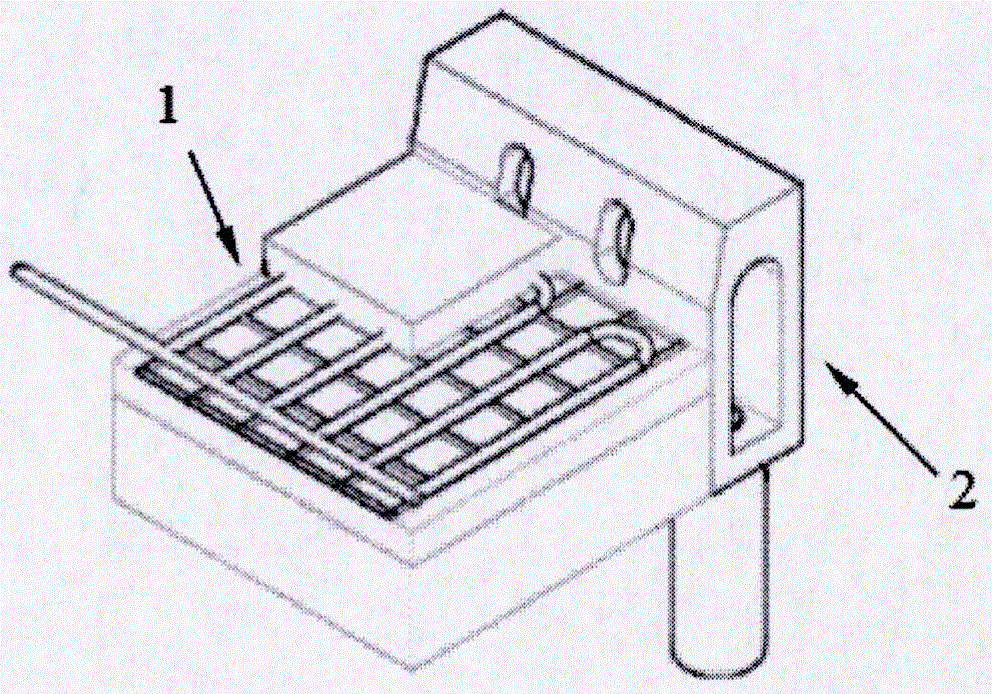
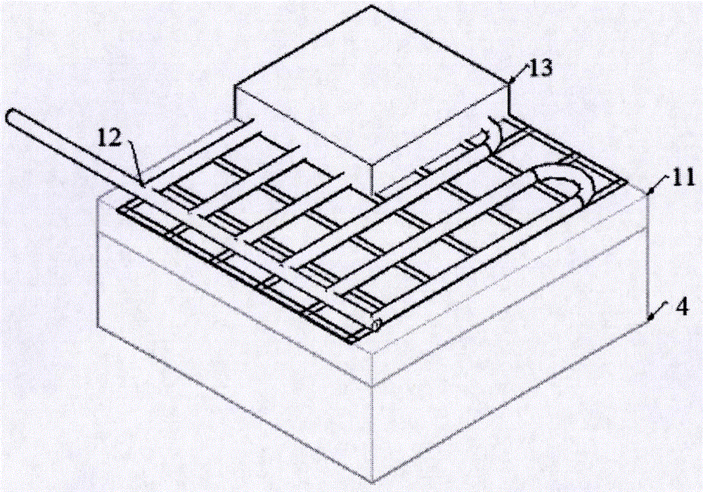
[0040] A snow melting system for asphalt concrete pavement, such as Figure 1-3 As shown, it includes a snow melting device 1, a drainage device 2 and a power supply device. In this embodiment, the power supply device is a solar power supply device 3; the snow melting device 1 is laid on the roadbed 4 and is electrically connected to the solar power supply device 3; The drainage device 2 is partly located on the road surface and partly located under the road surface, and is in close contact with the snow melting device 1 ; the ice and snow on the road surface is discharged into the ground through the drainage device 2 after being melted by the snow melting device 1 .

[0041] Specifically, the drainage device 2 is located at the lowest end of the road surface slope extension direction, so that the melted snow water can flow into the drainage device along the road surface slope direction from high to low. Generally speaking, there are multiple drainage devices, which can be even...

Embodiment 2

[0046] Such as Figure 6 As shown, the difference between this embodiment and Embodiment 1 is that the snow melting system also includes a monitoring device 5, and the monitoring device 5 includes an infrared thermal imager 51, a video monitor 52, a microprocessor 53 and a power distribution control box 54, the infrared thermal imager 51, the video monitor 52, and the microprocessor 53 are all electrically connected to the power distribution control box 54, and the power distribution control box 54 is electrically connected to the solar power supply device 3; the infrared thermal imager 51 and video monitor 52 are used to image the snowmelt condition on the road surface, and the imaging data is transmitted to the microprocessor 53 through the wireless communication device 55, and the microprocessor 53 processes the imaging data and transmits the processing result to the power distribution control Box 54 , the power distribution control box 54 is connected with the snow melting...

Embodiment 3

[0048] Such as Figure 7 As shown, the difference between this embodiment and Embodiment 2 is that the bottom of the drain main body 21 is also provided with a second heating wire 213, and the second heating wire 213 is partially buried in the drain main body 21, and part of it is exposed and It is connected with the second cable 214, and the second cable 214 is connected with the solar power supply device 3. The reason for embedding the second heating line 213 at the bottom of the drain main body 21 in this embodiment is that in the severe cold region of the north, the aboveground temperature can reach -20°C to -30°C in winter, and the area within 2m underground is below zero, and the snow After water enters the gutter, it may freeze again and block the water outlet 212. Therefore, a second heating line 213 is embedded near the water outlet 212 at the bottom of the gutter main body 21 to melt the ice and snow in the gutter and make the gutter drain. unobstructed.


PUM


Abstract

The invention relates to a snow melting system for an asphalt concrete pavement. The snow melting system for the asphalt concrete pavement comprises a snow melting device, a water drainage device and a power supply device, the snow melting device is paved on a roadbed and is electrically connected with the power supply device, the snow melting device uses a carbon fiber as a heat generating line, part of the water drainage device is located above the pavement, part of the water drainage device is located below the pavement, the water drainage device is in close contact with the snow melting device, and ice and snow on the pavement is melt by the snow melting device and then drained to the underground through the water drainage device. The clean energy is combined with the heat generating line of the carbon fiber, so that on one side, the problems of energy shortage and environmental pollution are solved, on the other side, the characteristics of high calorific value and stable heat generation of the carbon fiber are utilized, the snow melting effect is good, the labor cost and the equipment maintenance cost are not needed in the later period, and the snow melting system for the asphalt concrete pavement does not pollute the environment, and does not damage the pavement.

Description

technical field [0001] The invention relates to a snow melting system, in particular to an asphalt concrete road surface snow melting system. Background technique [0002] In the cold winter, snowfall and icing on the road surface are common as a natural phenomenon, especially in northern my country for a long time, which often affects the use of the road surface. Snow accumulation and icing will cover the road markings, reduce the friction coefficient of the road surface, etc. Therefore, on ice and snow roads, vehicles are prone to skidding and deviation, and the braking distance is significantly prolonged, which seriously affects the operational stability and safety of the vehicle, and the incidence of traffic accidents is high. Many pavements cannot be used normally due to heavy snow in winter, therefore, the snow melting and deicing of pavement cannot be ignored. Traditional manual and mechanical deicing technologies have low efficiency and cannot quickly meet the need...

Claims


Application Information

Patent Timeline
IPC IPC(8): E01C11/26E01C11/24E01C11/22
CPCE01C11/227E01C11/245E01C11/265
Inventor 高志斌张长安王树军王跃
Owner 高志斌
Why Eureka
Try Eureka