
Winter time-controlled type ventilation window of concentrating photovoltaic electric heating coupling ventilation system

A concentrating photovoltaic and electrothermal coupling technology, applied in the field of ventilation windows, can solve the problems of shortened battery life, incompatibility of ventilation and heat preservation effects, and decreased conversion rate of photovoltaic cells, so as to achieve clean air and pollution-free, easy to clean and maintain , The effect of reducing the heating load

Active Publication Date: 2017-06-13
NORTHEAST GASOLINEEUM UNIV
View PDF8 Cites 11 Cited by
  • Summary
  • Abstract
  • Description
  • Claims
  • Application Information

AI Technical Summary

Problems solved by technology

The photovoltaic panel of the ventilation window is located on the upper part of the window. If the waste heat generated cannot be effectively eliminated, the conversion rate of photovoltaic cells will decrease and the battery life will be shortened.
[0010] In order to ensure ventilation without opening windows in winter, and at the same time, to meet the indoor heating load without a substantial increase, the electric energy output by photovoltaic panels and the waste heat generated are fully utilized to solve the ventilation and indoor heat preservation effects of windows in winter incompatibility issue

Method used


Image

  • Winter time-controlled type ventilation window of concentrating photovoltaic electric heating coupling ventilation system
  • Winter time-controlled type ventilation window of concentrating photovoltaic electric heating coupling ventilation system
  • Winter time-controlled type ventilation window of concentrating photovoltaic electric heating coupling ventilation system

Examples


Embodiment Construction

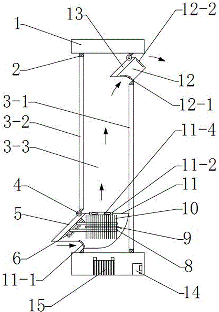
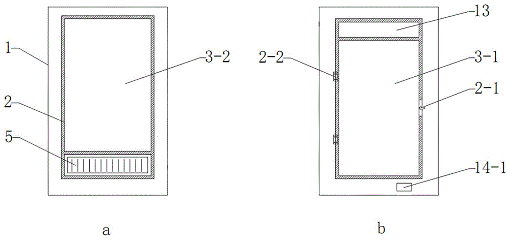
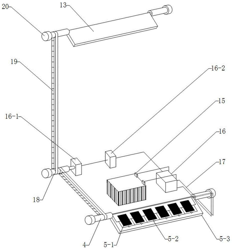
[0032] The specific implementation manners of the present invention will be further described in detail below in conjunction with the accompanying drawings. The accompanying drawings are simplified schematic diagrams used to illustrate the basic structure, key components and main uses of the present invention, so the embodiments of the present invention are not limited thereto.

[0033] a kind of like figure 1 — Figure 9 The ventilation window of the time-controlled photovoltaic electrothermal coupling ventilation system shown in winter consists of a window assembly, a concentrated photovoltaic cell panel 5, an air outlet baffle 13, a control device, a driving device, an air inlet heating assembly and a noise reduction filter channel box 12 Composition, each part is assembled and fixed to form a whole.

[0034] Such as figure 2 and image 3 As shown, the main structure of the window assembly is an integrated window frame 1 of PVC material type, the outdoor side sash 2 is...


PUM


Abstract

The invention discloses a winter time-controlled type ventilation window of a concentrating photovoltaic electric heating coupling ventilation system. The ventilation window comprises a window body assembly, a concentrating photovoltaic cell plate (5), an air port baffle (13), a control device, a driving device, an air inlet heating assembly and a noise reduction filter channel box (12). The window body assembly comprises an integrated window frame (1), a window sash (2) and two pieces of hollow glass on the two sides. A heat preservation and ventilation flow channel (3) is formed between the two pieces of hollow glass. The control device comprises a photovoltaic controller (14) and an accumulator (15). The driving device comprises a servo motor set, synchronous drive shafts (18), a synchronous belt (19), rotating shafts (4) and fixed bearing seats (20). The air inlet heating assembly comprises an air inlet channel box (11) and a phase change heat pipe-electric heat pipe complementary heat sink. The electric energy and waste heat of a photovoltaic cell are fully utilized, and meanwhile timing control over ventilation and fresh air heating is achieved, so that the problem that the ventilation effect of the window is incompatible with the indoor heat preservation effect is solved.

Description

[0001] Technical field [0002] The invention belongs to the integration of solar photovoltaic and building, and in particular relates to a ventilation window of a time-controlled concentrating photovoltaic electrothermal coupling ventilation system in winter. Background technique [0003] With the rapid development of my country's economy, people's focus on the living environment gradually tends to pursue the quality of health and comfort. In winter, if the windows are closed for a long time, the indoor air will become dirty due to lack of circulation, which will affect human health. It is necessary to open the windows for ventilation, and opening the windows, with the inflow of low-temperature air, will not only increase the indoor heating load , causing greater energy consumption and affecting comfort, and if the air is mixed with dust and pollutants, it will still affect human health and cause harm. Especially in northern rural areas, because the heating methods are mostl...

Claims


Application Information

Patent Timeline
IPC IPC(8): E06B7/02E06B3/66H02J7/35F24F7/013B01D46/12
CPCB01D46/12H02J7/35F24F7/013E06B3/66E06B7/02B01D46/645
Inventor 李栋王迪刘昌宇齐晗兵刘晓燕吴国忠
Owner NORTHEAST GASOLINEEUM UNIV
Learn More