Active optical cable connector, active optical cable assembly and photoelectric conversion unit

A photoelectric conversion unit and connector technology, applied in optical components, light guides, optics, etc., can solve the problems of glue flowing to the non-bonded surface, easy damage to electrical components, and difficulty in ensuring the consistency of the bonding process. The effect of improving rework performance

Active Publication Date: 2017-06-13
CHINA AVIATION OPTICAL-ELECTRICAL TECH CO LTD
View PDF4 Cites 5 Cited by
  • Summary
  • Abstract
  • Description
  • Claims
  • Application Information

AI Technical Summary

Problems solved by technology

For example, an active optical cable connector disclosed in a Chinese patent application with the application publication number of CN104330857 A and the application publication date of 2015.02.04, the connector includes a connector housing assembly, and the front end of the active optical cable connector is an electric plug. The electric plug housing and the connector housing constitute the connecting housing assembly of the active optical cable connector. The connector housing is rotated and equipped with a connecting nut, and the connecting nut passes through the external thread on the outer circumference of the rear end of the electric plug housing. Cooperate to connect the electric plug shell and the connector shell together, the photoelectric conversion unit is installed in the inner cavity of the rear end of the electric plug shell, the front printed board of the photoelectric conversion unit is welded and fixed on the contact piece of the electric plug, and the rear printed The printed board is fixed by glue filling, so that if the printed board fails during use, it cannot be disassembled and repaired
There is also an active optical cable connector that glues the photoele

Method used


Image

  • Active optical cable connector, active optical cable assembly and photoelectric conversion unit
  • Active optical cable connector, active optical cable assembly and photoelectric conversion unit
  • Active optical cable connector, active optical cable assembly and photoelectric conversion unit

Examples


Embodiment Construction

[0035] Embodiments of the present invention will be further described below in conjunction with the accompanying drawings.

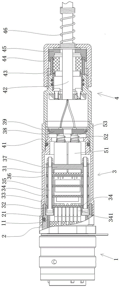
[0036] Specific embodiments of the active optical cable assembly of the present invention, such as Figure 2 to Figure 4 As shown, the active optical cable assembly includes an active optical cable and an active optical cable connector arranged at both ends of the active optical cable. The front part of the connector is the electrical plug 1 for the adaptive connection of the active optical cable connector, the rear part of the connector 3 is used to install and accommodate the photoelectric conversion unit, and the tail part 4 is used to fix the optical cable and has a waterproof sealing function.

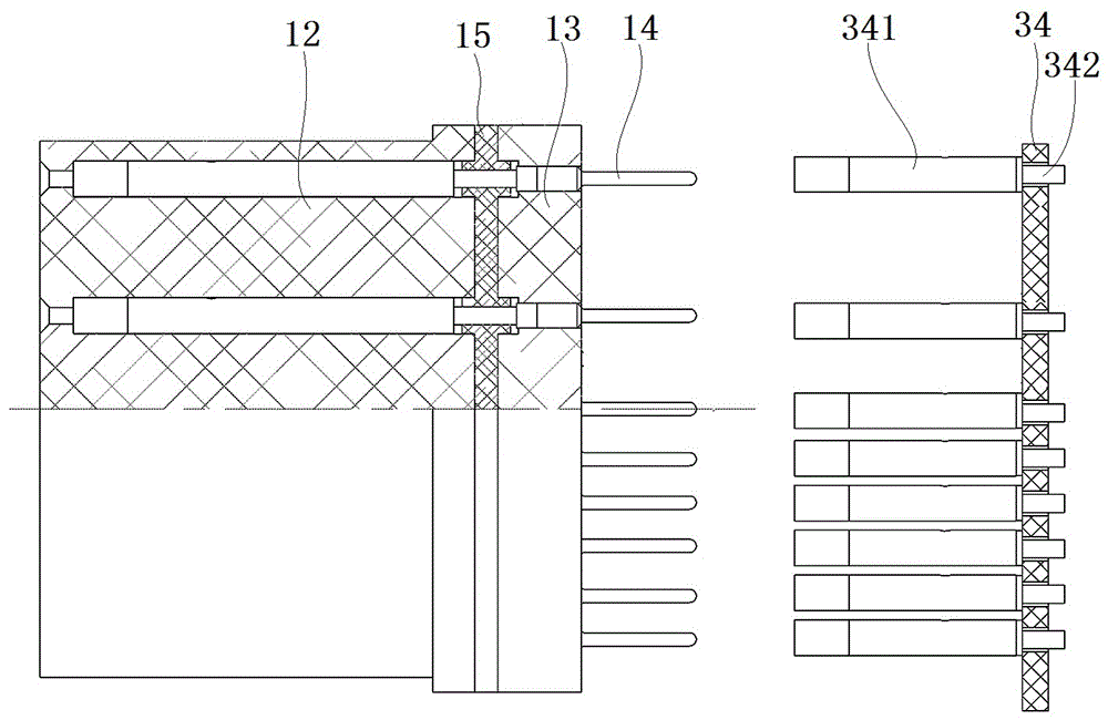
[0037] The electric plug 1 includes an electric plug housing 11 extending along the front-to-back direction, and an external thread is provided on the outer periphery of the rear end of the electric plug housing 11 . The rear part 3 of the connector is the ...


PUM


Abstract

The invention relates to an active optical cable connector, an active optical cable assembly and a photoelectric conversion unit. The active optical cable assembly comprises an active optical cable and active optical cable connectors arranged at two ends of the active optical cable, wherein each active optical cable connector comprises a connector shell assembly and a photoelectric conversion unit arranged in an inner cavity of the connector shell assembly; each photoelectric conversion unit comprises printed boards and a support part arranged between the printed boards, wherein the printed boards are arranged from front to back at an interval; and a fastening device is used for tightening or clamping the printed boards along the front and back direction, so that the printed boards are separated by dismantling the fastening device when the printed boards need to be repaired in the using process, and individual printed boards can be inspected, repaired or exchanged, thereby improving the repair performance of the active optical cable connectors.

Description

technical field [0001] The invention relates to an active optical cable connector, an active optical cable assembly and a photoelectric conversion unit. Background technique [0002] Optical fiber has been widely used in the communication industry due to its light weight, low loss, anti-electromagnetic interference and high transmission efficiency. Initially, optical fibers were connected by optical fiber connectors, but it was found that the contamination at the connection end faces of the optical fiber connectors would increase the loss of the optical fiber lines and even damage the optical fiber lines during use. In order to avoid the occurrence of the above situation, the user needs to check and maintain the optical fiber line within a fixed period through special instruments, which will consume a lot of manpower and material resources. [0003] The active optical cable connector strips the photoelectric conversion circuit from the device and integrates it into the conn...

Claims


Application Information

Patent Timeline
IPC IPC(8): G02B6/42
CPCG02B6/4219G02B6/4278G02B6/428
Inventor 周超蔡雷超殷向阳
Owner CHINA AVIATION OPTICAL-ELECTRICAL TECH CO LTD
Why Eureka
Try Eureka