Magnetic suspension energy storage flywheel charging and discharging control method based on minimum power topology

A charging and discharging control, energy storage flywheel technology, applied in the direction of AC network load balancing, etc., can solve the problems of inability to realize fast switching of charging and discharging, inability to realize power unit control, increase cost investment, etc., to avoid the installation of sensors and save energy. Resource and cost, the effect of improving reliability

Inactive Publication Date: 2017-06-13
BEIJING HONGHUI INT ENERGY TECH DEV CO LTD
View PDF3 Cites 20 Cited by
  • Summary
  • Abstract
  • Description
  • Claims
  • Application Information

AI Technical Summary

Problems solved by technology

But at the same time increase the hardware resources, increase the cost input
Moreover, this solution cannot achieve fast switching between charging and discharging, and there is a certain time disadvantage
Since the maglev energy storage flywheel is used in rail transit braking energy recovery and uninterrupted service power supply, the flywheel needs to be able to switch between charging and discharging at the millisecond level, so it cannot be achieved by independent power unit control

Method used


Image

  • Magnetic suspension energy storage flywheel charging and discharging control method based on minimum power topology
  • Magnetic suspension energy storage flywheel charging and discharging control method based on minimum power topology
  • Magnetic suspension energy storage flywheel charging and discharging control method based on minimum power topology

Examples


Embodiment 1

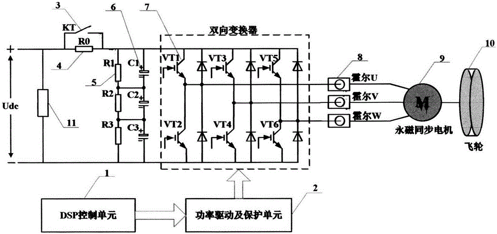
[0034] Embodiment 1: The minimum power topology of the present invention includes: DSP control unit, power drive and protection circuit, bypass relay, soft start resistor, voltage equalizing resistor, voltage stabilizing capacitor, IGBT switch tube, Hall current sensor, permanent magnet synchronous Motors, flywheels and DC loads. This method includes three working modes: charging mode, holding mode and discharging mode, and the specific implementation steps are as follows:

[0035] Charging mode: first step, the mains starts, and the DC Udc charges the voltage stabilizing capacitors C1, C2, and C3 through the soft-start resistor R0. At this time, the bypass relay KT is disconnected; the equalizing resistors R1, R2, and R3 are used to ensure that each The regulated voltage is divided and balanced to prevent overvoltage breakdown of the capacitor.

[0036] In the second step, when the DC bus voltage Udc is higher than the set charging voltage, the DSP control unit sends a start...

Embodiment 2

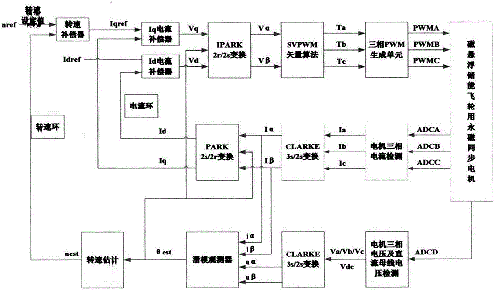
[0042] Embodiment 2: The charging mode control structure is composed of a speed outer loop and a double current inner loop. The control functions of each loop are as follows:

[0043] Speed ​​loop: The function is to maintain a constant speed. The speed setting value nref and the speed estimated value nest are made to make a difference. The speed error is transmitted to the speed compensator to obtain the Iq current reference value Iqref, which is used to generate effective electromagnetic torque.

[0044]Current loop: the function is to keep the Iq and Id currents constant, so that the motor current is used to generate electromagnetic torque without excitation torque. The Iq current loop makes a difference between the reference value Iqref generated by the speed loop and the measured value Iq, and the current error is input to the current compensator to obtain a voltage Vq, while the Id current loop makes a difference based on the reference value Idref and the measured value I...

Embodiment 3

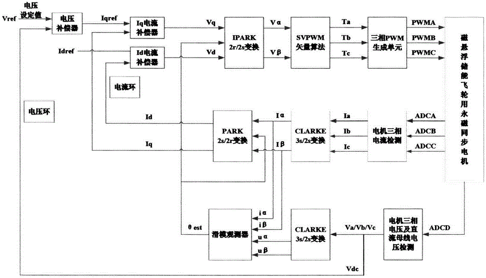
[0047] Embodiment 3: The discharge mode control structure is composed of a voltage outer loop and a double current inner loop. The control functions of each loop are as follows:

[0048] Voltage loop: the function is to maintain the DC bus voltage constant, the difference between the voltage setting value Vref and the DC bus voltage detection value Vde, the voltage error is transmitted to the voltage compensator to obtain the Iq current reference value Iqref, which is used to generate effective electromagnetic torque.

[0049] The contents of the current loop, measurement loop and estimation loop are the same as those in Embodiment 2, the difference is that the estimation loop only needs to obtain the estimated value θest of the angular position.

[0050] as attached Figure 4 Shown is the UV line voltage and U-phase current waveforms when the magnetic levitation energy storage flywheel of the present invention is used for charging control. It can be seen from the figure that...


PUM


Abstract

The invention discloses a magnetic suspension energy storage flywheel charging and discharging control method based on minimum power topology, and is used for finishing the high-efficient magnetic suspension energy storage flywheel charging and discharging control to realize the energy conversion of electric energy-kinetic energy-electric energy. The power topology comprises a DSP (Digital Signal Processor) control unit, a power driving and protecting circuit, a bypass relay, a soft boot resistor, an equalizing resistor, a voltage stabilization capacitor, an IGBT (Insulated Gate Bipolar Translator) switching tube, a Hall current sensor, a permanent magnet synchronous motor, a flywheel and a direct-current load, wherein the IGBT switching tube is under a high-frequency inversion state when direct-current bus voltage Udc is higher than charging voltage, a permanent magnet synchronous motor drives the flywheel to be accelerated, and the flywheel is under a charging mode to finish the conversion of the electric energy to kinetic energy; when the direct-current bus voltage Udc is lower than discharging voltage, the IGBT switching tube is under a PWM (Pulse-Width Modulation) rectification state, the revolving speed of the flywheel is lowered, and the permanent magnet synchronous motor is under a discharging mode to finish the conversion of the kinetic energy to the electric energy. The magnetic suspension energy storage flywheel charging and discharging control method is used for the high-efficient magnetic suspension energy storage flywheel charging and discharging control.

Description

[0001] Technical field: [0002] The invention relates to a charging and discharging control method of a magnetic levitation energy storage flywheel based on a minimum power topology. [0003] Background technique: [0004] Compared with other energy storage methods, the magnetic levitation flywheel energy storage technology has the advantages of rapid charging and discharging, high power, high energy density, long life and little environmental pollution. It is an emerging and advanced mechanical energy storage method. There are better applications in peak shaving, rail transit braking energy recovery, uninterruptible power supply, and high-power charging and discharging. Due to the advantages of simple structure, small size, high power factor, high power density, and low moment of inertia, it is an ideal choice to use a high-speed permanent magnet synchronous motor to drive the flywheel rotor to complete the charge and discharge control process. [0005] Based on the differen...

Claims


Application Information

Patent Timeline
Patent Type & Authority Applications(China)
IPC IPC(8): H02J3/30
CPCH02J3/30Y02E60/16
Inventor 李树胜王志强刘金晶李迁李云龙
Owner BEIJING HONGHUI INT ENERGY TECH DEV CO LTD
Why Eureka
Try Eureka