
Electromagnet-friction piezoelectric composite energy harvester

An energy harvester and composite technology, which is applied in the directions of triboelectric generators, generators/motors, piezoelectric effect/electrostrictive or magnetostrictive motors, etc., can solve the problems of low harvesting efficiency and achieve energy harvesting efficiency High, increased output, convenient design effect

Active Publication Date: 2017-06-13
JILIN UNIV
View PDF22 Cites 24 Cited by
  • Summary
  • Abstract
  • Description
  • Claims
  • Application Information

AI Technical Summary

Problems solved by technology

[0004] The present invention proposes an electromagnetic friction piezoelectric composite energy harvester to solve the problem of low collection efficiency in traditional single-form and composite-form energy harvesters

Method used


Image

  • Electromagnet-friction piezoelectric composite energy harvester
  • Electromagnet-friction piezoelectric composite energy harvester
  • Electromagnet-friction piezoelectric composite energy harvester

Examples


Embodiment Construction

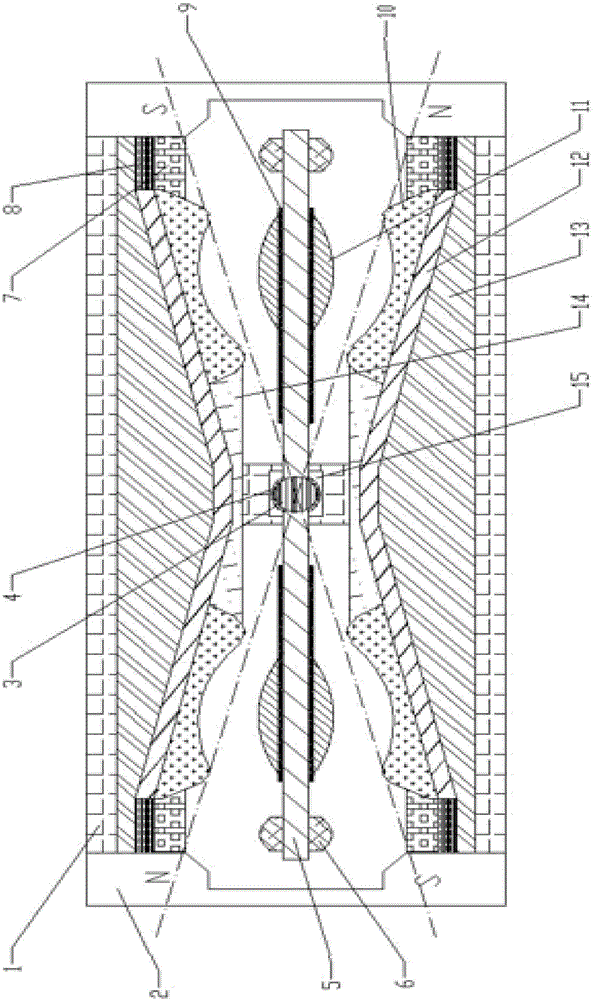
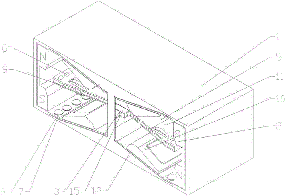
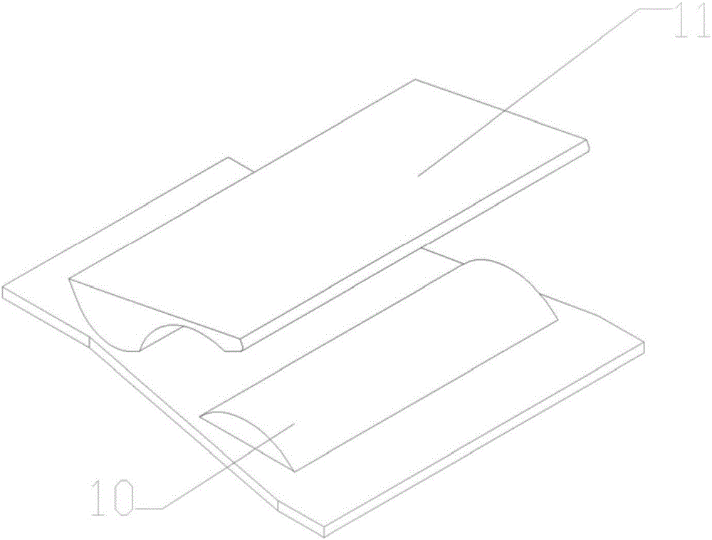
[0022] The two sides of the collector housing 1 are symmetrically equipped with "gate"-shaped permanent magnets 2 with opposite magnetic poles. The rotating shaft 3 is connected to the housing 1 through the bearing 4. The concave cantilever beam 5 is fixedly connected to the rotating shaft 3. The two ends of the cantilever beam 5 are respectively fixedly connected to the hemispherical mass block 6, and the piezoelectric ceramic 8 covered with the buffer layer 7 corresponds to the mass block 6 one by one, and is installed inside the housing 1. A coil 9 is wound on the cantilever beam 5, and the coil 9 9 is attached with a second friction layer 11, and the corresponding positions between the second friction layer 11 and the housing 1 are the first friction layer 10, the flexible piezoelectric material 12 and the insulating filling layer 13, and the collected energy passes through the first electrode Layer 14 and the second electrode layer 15 are externally connected to the line o...


PUM


Abstract

The invention relates to an electromagnet-friction piezoelectric composite energy harvester and belongs to the technical fields of micro-electro-mechanical systems and micro energy. Permanent magnets are placed on the two sides in a shell of the harvester, a rotary shaft is connected with the shell through a bearing, a cantilever beam in an internal dent shape is fixedly connected to the rotary shaft, and the two ends of the cantilever beam are fixedly connected with hemispherical mass blocks respectively. Piezoelectric ceramics coated with a buffer layer are installed in the shell, a coil is wound around the cantilever beam, a second friction layer is attached to the exterior of the coil, and a first friction layer, a flexible piezoelectric material and an insulated filling layer are sequentially arranged on the corresponding positions between the second friction layer and the shell. Harvested energy is output through external lines of a first electrode layer and a second electrode layer, the first electrode layer is connected with the flexible piezoelectric material and the first friction layer, and the second electrode layer is located on the upper portion of the rotary shaft, and connected with the coil and the second friction layer through wires. The electromagnet-friction piezoelectric composite energy harvester has the advantages that vibrational energy is converted into electric energy, the output energy is amplified in a summed mode, and the energy conversion efficiency of the harvester is further improved.

Description

technical field [0001] The invention relates to the technical fields of micro-electromechanical systems (MEMS) and micro-energy sources, in particular to an electromagnetic-friction-piezoelectric composite energy collector. Background technique [0002] With the increasing trend of energy cleanliness and high efficiency, the research work on new energy harvesting devices has made great progress in recent years. Vibration energy harvester is a research focus of new energy harvesting devices, and its working methods mainly include electromagnetic, electrostatic and piezoelectric. In terms of electromagnetic type, Kulah et al., a research group of Middle East Technical University in Turkey, proposed a method of cantilever beam array with different natural frequencies to increase the resonance bandwidth, so that the energy of vibration signals with a wider frequency band can be collected; in terms of electrostatic type, Academician Wang Zhonglin Realized the TENGs nano triboele...

Claims


Application Information

Patent Timeline
Patent Type & Authority Applications(China)
IPC IPC(8): H02K35/04H02N1/04H02N2/18
CPCH02K35/04H02N1/04H02N2/186
Inventor 杨旭马志鹏姚姝琬何文松徐克菲
Owner JILIN UNIV
Learn More