Supercharge Your Innovation With Domain-Expert AI Agents!

Isolated capacitive power transfer

A technology of permanent power and capacitance, applied in the conversion of DC power input to DC power output, AC power input into DC power output, output power conversion device, etc., can solve the problem of no power efficiency and achieve functional efficiency improvement, Effect of small die area and cost reduction

Active Publication Date: 2017-06-13
TEXAS INSTR INC
View PDF8 Cites 0 Cited by
  • Summary
  • Abstract
  • Description
  • Claims
  • Application Information

AI Technical Summary

Problems solved by technology

These existing options cannot meet the above size requirements because of the large amount of space necessary to implement the transformer, with several isolated power supply units ranging from 7×7mm 2 to 15×15mm 2 changing size
Also, existing options have no power efficiency in the low power region, where efficiency varies from 10% to 40% at 25mW

Method used


Image

  • Isolated capacitive power transfer
  • Isolated capacitive power transfer
  • Isolated capacitive power transfer

Examples


Embodiment Construction

[0027] Reference will now be made in detail to specific embodiments of the invention which are illustrated in the accompanying drawings. In the following detailed description of the embodiments of the present invention, numerous specific details are set forth in order to provide a more thorough understanding of the present invention. It will be apparent, however, to one skilled in the art that the present invention may be practiced without these specific details. In other instances, well known features have not been described in detail to avoid unnecessarily complicating the description.

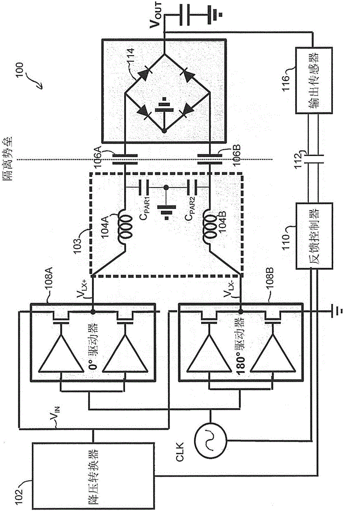
[0028] Referring now to the drawings, and more particularly to figure 1 , shows a schematic diagram of an example system 100 for power transfer across an isolation barrier according to an embodiment of the invention. In system 100, buck converter 102 receives an input voltage (not specifically shown), which is stepped down to a level usable by series resonant circuit 103 of the power deli...


PUM


Abstract

The invention relates to an isolated capacitive power transfer. A method and device for providing isolated power transfer to a low-power load across a capacitor of a series resonance circuit are shown. The method includes comparing an output voltage received via a feedback loop with a desired output voltage. Responsive to determining that the output voltage is not equal to the desired output voltage, the method determines a sub-harmonic order of the resonant frequency of the series resonance circuit to use as a switching frequency and switches the series resonance circuit at substantially the determined subharmonic order of the resonant frequency.

Description

[0001] Priority claims and related patent applications [0002] This non-provisional application claims priority over the following prior U.S. provisional patent applications: (i) by Lei Chen, Rajarshi Mukhopadhyay, and Mark W. Morgan ), Application No. 62 / 244,224, "HARMONIC CAPACITIVE POWERTRANSFER," filed October 21, 2015; said application is hereby incorporated by reference in its entirety. technical field [0003] The disclosed embodiments relate generally to the field of power transfer. More particularly, and without limitation, the present invention relates to improving the efficiency of low power capacitive power transfer. Background technique [0004] In industrial sensor applications for sensing temperature or pressure, for example, it is necessary to isolate the power supply from the analog front end for safety and protection of the equipment. The power interface requires immunity to common mode transients which may be higher than 100KV / μs, necessitating high vo...

Claims


Application Information

Patent Timeline
Patent Type & Authority Applications(China)
IPC IPC(8): H02M3/335
CPCH02M3/33507H02M3/33515H02M3/01H02M3/33571H02M3/158H02M3/28H02M7/217Y02B70/10H02M1/123
Inventor 陈雷拉贾尔什·穆霍帕德亚马克·W·摩根约瑟夫·A·桑克曼
Owner TEXAS INSTR INC
Features
  • R&D
  • Intellectual Property
  • Life Sciences
  • Materials
  • Tech Scout
  • Unparalleled Data Quality
  • Higher Quality Content
  • 60% Fewer Hallucinations
Learn More